Sponsored

Generac 6854 with 120 VAC input

ZeusDriver

Well-known member
Joined
Dec 1, 2025
Threads
9
Messages
203
Reaction score
174
Location
East Coast, USA
Vehicles
2022 Lightning
The short version of what's below:
Has anyone here used a 120 VAC input (such as from a "power bank" inverter, or the 120 VAC outlets on a standard short range XLT) to operate a Generac 6854? Generac tech support was of no use. I have the unit wired up, and it will serve my needs, but the push button operation of the main switch does not work so far. Many "power banks" (battery/inverter units) output 120, but not 240, and this switch would be useful for connecting those to a home to feed essential services. Also, it would be useful to enable my Lightning to feed those services, which it could do for about a week or more.

The painfully long version:
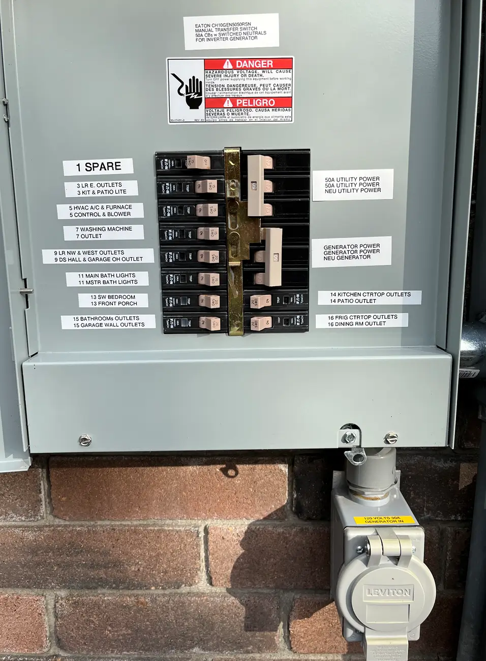
I ordered the Generac 6854 via Amazon. According to the Amazon listing, this 30 A version operates on 120 VAC, whereas the 50 amp version operates on 240 VAC.

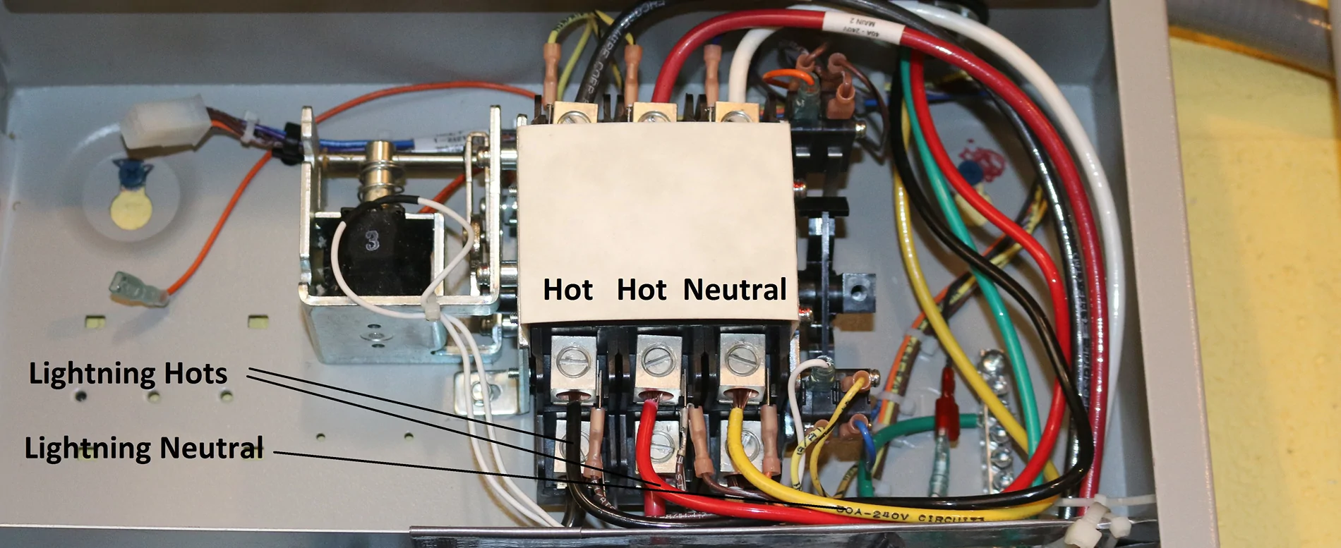
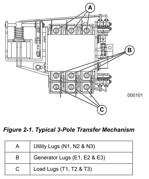
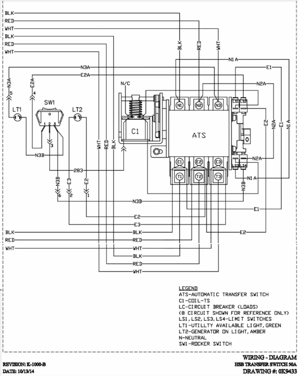
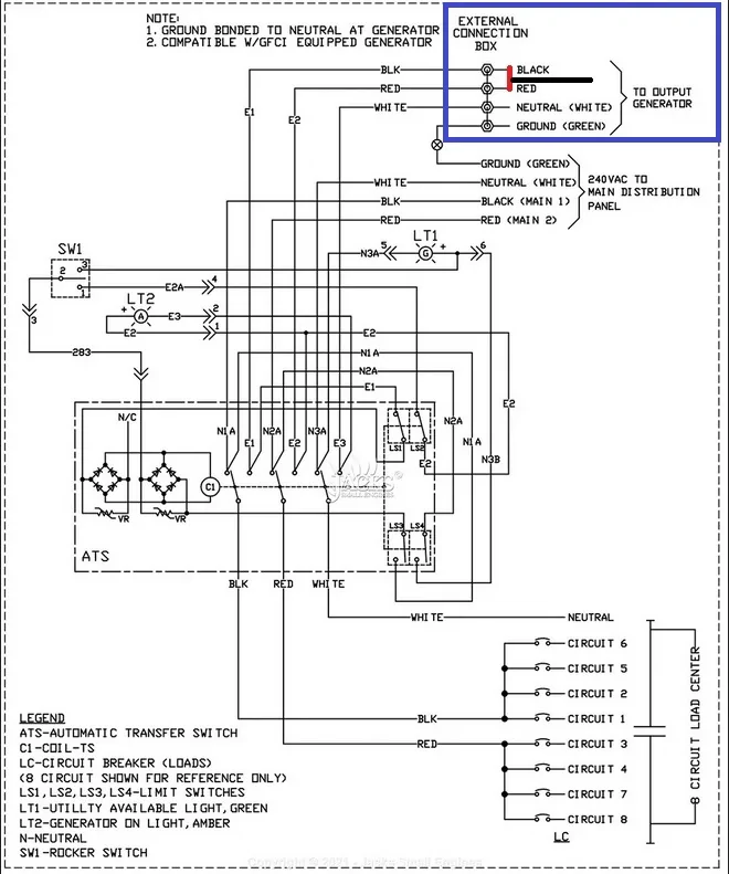
However, the owner's manual says it only operates with a 240 VAC input. (These switches are "manual" but the mechanical movement of the main switch itself can be accomplished via a pushbutton that causes a solenoid to operate, which yanks on the switch linkage.) The manual and other paperwork that comes with the switch does not provide a schematic -- just somewhat crude wiring diagrams that do not, for instance, show what happens inside any of the devices (which are mainly just switches). From tracing wires, I could see that the indicator lamps on the panel are 120 vac, but as the unit is wired, the solenoid that switches from one mode to the other runs on 240 VAC.

The solenoid that yanks on the main switch to change modes, has four leads, which I first thought were there for convenience (two for each end of the solenoid coil), but I suspect that the coil may be dual voltage, and getting it to work on 120 may be as simple as plugging in the right leads.

The Generac tech went on at some length about his plan to charge an electric vehicle with an onboard wind turbine. (I have met similar types who have suggested just turning on regen to charge as you drive... or just tow a trailer with one wheel connected to a generator... etc, etc. ... all perpetual motion schemes.) He also appeared to know nothing about the product itself, and thought that if I hooked it up to 120 VAC from my truck, that the truck would blow up. I'd hoped he could send me a real schematic, but he could not.

Instead of sending the unit back, I tested it, and everything works fine, provided I move the main switch by hand (they provide a little lever for that purpose).

The weather outside is frightening... so the panel is live, and I try not to do much work on live panels. But pulling a couple leads off the solenoid indicates that it is not wired as I had assumed, with there being 8.8 ohms (a coil with a lot of turns) between the orange leads (that I had assumed were joined at one end of the coil... given that there is no good way of telling them apart.) I can certainly get the solenoid working, possibly just by switching leads around, but I thought that someone here may have already done this, and you could save me some investigative work.

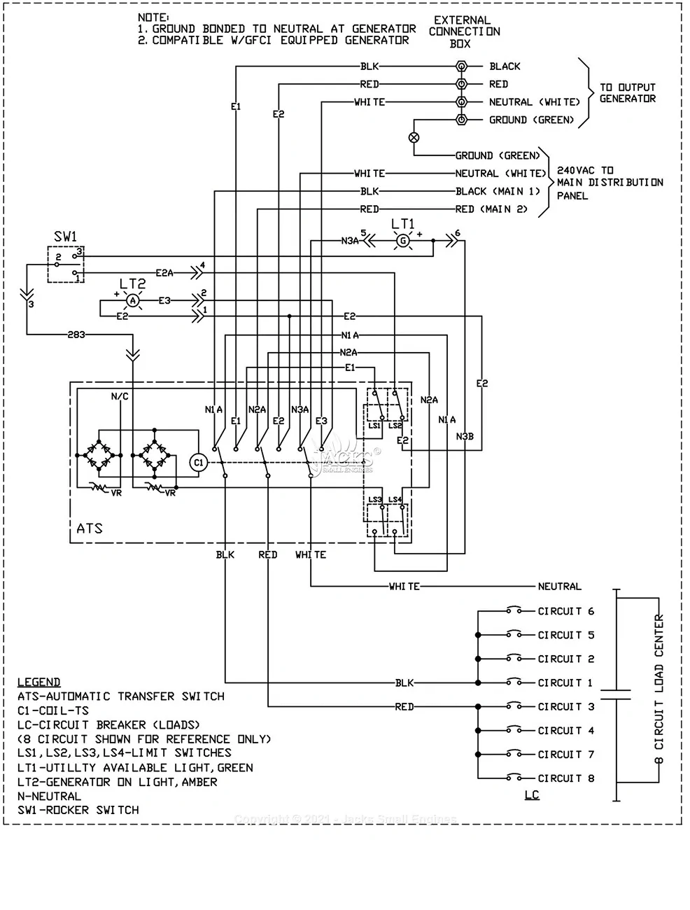
A long search produced a thread (at gentekpower.com) that indicated that several people had the issue of the buttons not working correctly. At least one of these people was trying to make the switch work with a 120 vac source. Another was using a Generac generator (which outputs 240 vac) but was having the same issue, and he'd found tech support useless, too. In that thread, however, there was a far better wiring diagram than my manual has... not a real schematic with each switch contact shown, but at least with the wires from device to device shown accurately.
Sponsored


chl

Well-known member
First Name
CHRIS
Joined
Dec 16, 2022
Threads
7
Messages
2,728
Reaction score
1,694
Location
alexandria virginia
Vehicles
2023 F-150 LIGHTNING, 2012 Nissan Leaf, 2015 Toyota Prius, 2000 HD 883 Sportster
Occupation
Patent Atty / Electrical Engineer
The short answer, no the button switch will not work with 120V, unless you wire the generator input so the 120v hot lead connects to both hots posts inside the generac where for 240V you would have 2 hots connected.

Without getting into too much detail, normally the solenoid switch activates when pushed only if there is 240V at either the utility or the generator input, or both. It is designed to accept 240V with two hot wires, one neutral and one ground wire input.

Not sure how you wired yours, but if you only used one of the hot leads inside the generac, that might be the problem. You might need to have the 120v hot connected to the two 240V hot connections inside the generac. I never tried that so not sure it would work.

You could just return it to Amazon and get this 120V transfer switch or something like it would be my suggestion:

120V 30A 6-Circuit Non-Automatic Transfer Switch

• Safe Manual Power Switching: Provides a secure, non-automatic way to connect your generator to your home’s electrical system, giving you full control over power during an outage.
• 30A Power Capacity with Flexible Circuit Support: Rated for 30 amps at 120V, supporting up to 6 circuits to power essential home loads.
• Precise Circuit Control & Load Management: Manual selector switches allow you to choose and manage specific circuits efficiently while preventing backfeeding and protecting your electrical system.
• Durable, Installation-Ready Construction: Built with a rugged steel enclosure and illuminated rocker switches that clearly indicate generator power status for safe, reliable operation.
• Complete Generator Connection Kit: Includes a L5-30P 30A power inlet, 30A power cord and pre-wired components to simplify installation with compatible generator systems.
• Certified for Safety & Code Compliance: Independently tested and certified to meet UL 1008 and CAN/CSA C22.2 No. 178.1 standards, with compliance verified under ISO/IEC Guide 17067 for safe, code-compliant operation.

https://naturesgenerator.com/products/natures-generator-power-transfer-kit-elite
 
Last edited:

chl

Well-known member
First Name
CHRIS
Joined
Dec 16, 2022
Threads
7
Messages
2,728
Reaction score
1,694
Location
alexandria virginia
Vehicles
2023 F-150 LIGHTNING, 2012 Nissan Leaf, 2015 Toyota Prius, 2000 HD 883 Sportster
Occupation
Patent Atty / Electrical Engineer
PS: you will not get 120V 30A from the Lightning, but you can get 120V 20A.

I have a GENERAC 6853 (the same as the 6854 but different inlet box kit) that I use with the Lightning PPOB 240V 30A bed outlet for home backup,

Rewiring the GENERAC solenoid: the solenoid operates on 120V so to get it to work with a 120v input you might just need to wire the 120v input so both generator input hots are connected to the 120V hot.

Below is one wired for 240V from a Lightning PPOB with the Black and Red hot wires and a Yellow neutral wire (middle of the picture), the top Red, Black and White wires are from the utility.

Not sure how you wired the utility power - three wire 240V or 120V?

Anyway the idea is that the 120V hot would be connected to where the Red and Black wires are connected.

However, the 6853 manual does not explain how to use the transfer switch with 120V so I am just guessing that is what you might try.

If you try this, do it without having the Generac utility lines connected or the load, just in case.

Ford F-150 Lightning Generac 6854 with 120 VAC input IMG_5929-Generac 6853-cro


So if the two labelled Lightning Hot were both connected to the 120V input hot, it might work.

I am an electrical engineer but not a licensed electrician, so check with a qualify electrician before implementing your system.
 
Last edited:

chl

Well-known member
First Name
CHRIS
Joined
Dec 16, 2022
Threads
7
Messages
2,728
Reaction score
1,694
Location
alexandria virginia
Vehicles
2023 F-150 LIGHTNING, 2012 Nissan Leaf, 2015 Toyota Prius, 2000 HD 883 Sportster
Occupation
Patent Atty / Electrical Engineer
PPS: a search found this which is what I suggested might work:

Wiring for 120VAC Input

  1. Prepare the Power Inlet Box (PIB): Connect the 120V output from your generator to the power inlet box.
  2. Bridge the Hot Legs (120V to 240V Conversion):
    • Inside the NEMA 3R Aluminum Power Inlet Box (included in the kit), locate the X (L1) and Y (L2) terminals.
    • Install a jumper wire between terminal X and terminal Y.
    • Connect your 120V hot wire from the generator to one of these bridged terminals (X or Y).
  3. Connect Neutral and Ground:
    • Connect the Neutral wire to the Neutral (W) terminal.
    • Connect the Ground wire to the Ground (G) terminal.
  4. Confirming Connections: The L14-30 plug on the cord will now receive 120V on both hot legs, allowing the transfer switch to distribute 120V power to all 8–10 circuits
So essentially it is saying to connect the one HOT from the 120V source to the two HOT input terminals by bridging them inside the box.
 

Sponsored

chl

Well-known member
First Name
CHRIS
Joined
Dec 16, 2022
Threads
7
Messages
2,728
Reaction score
1,694
Location
alexandria virginia
Vehicles
2023 F-150 LIGHTNING, 2012 Nissan Leaf, 2015 Toyota Prius, 2000 HD 883 Sportster
Occupation
Patent Atty / Electrical Engineer
OK based on that circuit diagram, I believe you need 120V on both E1 and E2 to operate the coil (and the indicator light LT1 or LT2).

So to work with 120V, you need to tie the 120V input HOT to both E1 and E2, connect neutral to E3, and connect the Ground wire to Ground bus (not shown in diagram but inside the GENERAC).

The generator lugs B are for wires E1, E2 and E3 in a 240v configuration.
For 120V, E1 and E2 would both have the 120V hot and E3 the 120V neutral wire, that is E1 and E2 would be tied together.

Like this in the blue box:

Ford F-150 Lightning Generac 6854 with 120 VAC input for 120V operation


You could tie them together inside the GENERAC or in the input box like the search result suggested - if you do that be sure to label it FOR 120V ONLY so in the future no one plugs a 240v cord in by mistake.

It might be safer to tie them together in an adapter plug specifically for this use, rather than in the box or inside the GENERAC.

------------
Disclaimer

I am an electrical engineer but not a licensed electrician.

The information provided in this post is provided for information purposes only and does not constitute any endorsement or recommendation. No warranty, expressed or implied, is made regarding the accuracy, adequacy, completeness, legality, reliability, or usefulness of any information found in this post. It is your responsibility to verify and investigate this information.
 
OP
OP

ZeusDriver

Well-known member
Joined
Dec 1, 2025
Threads
9
Messages
203
Reaction score
174
Location
East Coast, USA
Vehicles
2022 Lightning
You could just return it to Amazon and get this 120V transfer switch or something like it would be my suggestion:
Hi Chi. Huge thanks for looking into this. Far more detail than I have any right to expect.

I wanted to have neutral switching (and one or two other features of the Generac switch) so I went ahead and wired it up. I can get the solenoid to work, I am sure, but might just make a hole in the cover to provide access for the manual operation rod. If I do that, I'll put an access plug in that hole.

With the same 120 v input to both E1 and E2, then the solenoid is fed 0 volts (the difference), and so does nothing. The solenoid is an odd bird, with the 2 full wave bridge rectifiers feeding it. (I don't know what the actual resistance across the variable resistors are, so dont know what the dc(ish) voltage to the coil is intended to be). When the weather warms up , I may remove the solenoid and put it on the bench and see what goes on with it. Before having the schematic that shows the rectifiers, I had incorrectly assumed that the coil was dual voltage, given the four wires feeding it, and given the 8.8 ohms across the orange wires. But no such luck.

With the two rectifiers, it seems plausible that the designer was thinking about setting the VR's differently, so that different AC voltages (util vs gen) could be used to operate the coil. The fact that Amazon sells the 30A switch as 120 v, (but the 50 A as 240) might be because of that... or it could just be an error.

Strangely, if I go to the Generac site and input my serial number for my switch (which is labeled 30A) the wiring diagram and schematic that comes up is for a 50 A switch.

For the time being, however, the switch is working fine, so I'll go ahead and wire it for real, with conduit, etc. (I didn't want to cut all the wires to length if I were going to return it. )
 
OP
OP

ZeusDriver

Well-known member
Joined
Dec 1, 2025
Threads
9
Messages
203
Reaction score
174
Location
East Coast, USA
Vehicles
2022 Lightning
if you do that be sure to label it FOR 120V ONLY so in the future no one plugs a 240v cord in by mistake.
Yes! Thanks again. I have a to do list, and failed to put that on it. I need to replace a 14 g wire with a 12, and a coupe other things, too.
 

Tired Lizard

Member
First Name
Gene
Joined
Jun 18, 2025
Threads
0
Messages
22
Reaction score
18
Location
Pearland, Texas
Vehicles
23 Maverick Hybrid, 22 Escape PHEV, 23 Bolt EUV
When I added a MTS after 2021 Texas Freeze, I just had a 120V 30A Inverter Generator.
I left the MTS wiring setup for 120/240VAC.
So now a few years later I can plug in my larger 120/240 Inverter Generator if I want.

For my 120V only Inverter Generator I made a power cord that is like a "dogbone" adapter.
TT-30 cord to the 30A Twist Lock Power Inlet with Hots(X,Y) bridged in the 30A cord cap.

Ford F-150 Lightning Generac 6854 with 120 VAC input 1770149834710-g


Ford F-150 Lightning Generac 6854 with 120 VAC input 1770149903484-9u

*Eaton discontinued the MTS I have.
 

Sponsored
OP
OP

ZeusDriver

Well-known member
Joined
Dec 1, 2025
Threads
9
Messages
203
Reaction score
174
Location
East Coast, USA
Vehicles
2022 Lightning
When I added a MTS after 2021 Texas Freeze, I just had a 120V 30A Inverter Generator.
I left the MTS wiring setup for 120/240VAC.
So now a few years later I can plug in my larger 120/240 Inverter Generator if I want.

For my 120V only Inverter Generator I made a power cord that is like a "dogbone" adapter.
TT-30 cord to the 30A Twist Lock Power Inlet with Hots(X,Y) bridged in the 30A cord cap.

1770149834710-ge.webp


1770149903484-9u.webp

*Eaton discontinued the MTS I have.
Sadly, when I went to the hardware store I picked up the wrong 30 A plug, thinking it looked like a TT30, which fits my inverter. But I had a heavy duty 20A plug which I wired to the inlet cord, and then did the bridging in the inlet box (not enough room in the 120 plug). Your method is better, because it would allow 240 input -- so I think that's what I will do before I have this all buttoned up.
 

chl

Well-known member
First Name
CHRIS
Joined
Dec 16, 2022
Threads
7
Messages
2,728
Reaction score
1,694
Location
alexandria virginia
Vehicles
2023 F-150 LIGHTNING, 2012 Nissan Leaf, 2015 Toyota Prius, 2000 HD 883 Sportster
Occupation
Patent Atty / Electrical Engineer
Hi Chi. Huge thanks for looking into this. Far more detail than I have any right to expect.

I wanted to have neutral switching (and one or two other features of the Generac switch) so I went ahead and wired it up. I can get the solenoid to work, I am sure, but might just make a hole in the cover to provide access for the manual operation rod. If I do that, I'll put an access plug in that hole.

With the same 120 v input to both E1 and E2, then the solenoid is fed 0 volts (the difference), and so does nothing. The solenoid is an odd bird, with the 2 full wave bridge rectifiers feeding it. (I don't know what the actual resistance across the variable resistors are, so dont know what the dc(ish) voltage to the coil is intended to be). When the weather warms up , I may remove the solenoid and put it on the bench and see what goes on with it. Before having the schematic that shows the rectifiers, I had incorrectly assumed that the coil was dual voltage, given the four wires feeding it, and given the 8.8 ohms across the orange wires. But no such luck.

With the two rectifiers, it seems plausible that the designer was thinking about setting the VR's differently, so that different AC voltages (util vs gen) could be used to operate the coil. The fact that Amazon sells the 30A switch as 120 v, (but the 50 A as 240) might be because of that... or it could just be an error.

Strangely, if I go to the Generac site and input my serial number for my switch (which is labeled 30A) the wiring diagram and schematic that comes up is for a 50 A switch.

For the time being, however, the switch is working fine, so I'll go ahead and wire it for real, with conduit, etc. (I didn't want to cut all the wires to length if I were going to return it. )
So you tested it and It didn't work...that was what basically what the 'dogbone' adapte @Tired-Lizard said worked for his system:

"For my 120V only Inverter Generator I made a power cord that is like a "dogbone" adapter.
TT-30 cord to the 30A Twist Lock Power Inlet with Hots(X,Y) bridged in the 30A cord cap...."


If it didn't work with the 120V hot tied to just one of the input line E1 or E2, then I thought it maybe would work with both tied together.

On further reflection I see that E2 connects back to the rectifiers at the other side of the coil from E1.

But then I wonder why it did not activate the coil when E2 was not connected but E1 and E3 (neutral) were?

You tried it with only E1 and E3 (120V hot and neutral) connected right?

Perhaps, like you suggested, the variable resistors VR have to be adjusted so that a 120V will activate the coil? They would adjust the coil current so that would make sense.

Too bad GENERAC can't explain this.
 

chl

Well-known member
First Name
CHRIS
Joined
Dec 16, 2022
Threads
7
Messages
2,728
Reaction score
1,694
Location
alexandria virginia
Vehicles
2023 F-150 LIGHTNING, 2012 Nissan Leaf, 2015 Toyota Prius, 2000 HD 883 Sportster
Occupation
Patent Atty / Electrical Engineer
Apparently, other folks have asked about this and the bridging didn't work with the GENERAC, so they ended up using the lever like you did (from an internet search I did).

Cutting a slot into the cover so it doesn't have to be left open would be what I'd do I guess, or just return it and get one that will work with 120v.
 

chl

Well-known member
First Name
CHRIS
Joined
Dec 16, 2022
Threads
7
Messages
2,728
Reaction score
1,694
Location
alexandria virginia
Vehicles
2023 F-150 LIGHTNING, 2012 Nissan Leaf, 2015 Toyota Prius, 2000 HD 883 Sportster
Occupation
Patent Atty / Electrical Engineer
You tried it with only E1 and E3 (120V hot and neutral) connected right?
Of course with E2 not connected (nor bridged) only one side of your transfer switch will be powered.

To have both columns of breakers power has to be bridged E1 and E2.

Why did GENERAC put the solenoid in there - it's a manual transfer switch after all?

Here is why the 6854 model uses a solenoid according to AI:

  • "OneTouch" Operation: Instead of requiring the user to manually move a heavy mechanical interlock lever to change power sources, the solenoid acts as an actuator that flips the connection mechanism when the button is pushed.
  • Safety & Back-feed Prevention: The solenoid ensures that the transfer mechanism fully engages with either the utility or the generator, preventing both from being connected simultaneously, which protects utility workers from dangerous back-feeding.
  • Future-Proofing (Upgradeability): The 6854 model is designed to be upgraded to an automatic transfer switch (ATS) later. The solenoid acts as the bridge between the manual, push-button control and the automatic,, electrical control of a full standby generator system.
  • Power Source Indicator: The solenoid works in conjunction with the system's electronics to illuminate indicator lights, letting the user know when generator power is available to switch to.
While the 6854 is labeled a "manual" switch, the solenoid acts as the "motor" that performs the physical switching action when activated by the use
 
OP
OP

ZeusDriver

Well-known member
Joined
Dec 1, 2025
Threads
9
Messages
203
Reaction score
174
Location
East Coast, USA
Vehicles
2022 Lightning
Of course with E2 not connected (nor bridged) only one side of your transfer switch will be powered.

To have both columns of breakers power has to be bridged E1 and E2.

Why did GENERAC put the solenoid in there - it's a manual transfer switch after all?

Here is why the 6854 model uses a solenoid according to AI:

  • "OneTouch" Operation: Instead of requiring the user to manually move a heavy mechanical interlock lever to change power sources, the solenoid acts as an actuator that flips the connection mechanism when the button is pushed.
  • Safety & Back-feed Prevention: The solenoid ensures that the transfer mechanism fully engages with either the utility or the generator, preventing both from being connected simultaneously, which protects utility workers from dangerous back-feeding.
  • Future-Proofing (Upgradeability): The 6854 model is designed to be upgraded to an automatic transfer switch (ATS) later. The solenoid acts as the bridge between the manual, push-button control and the automatic,, electrical control of a full standby generator system.
  • Power Source Indicator: The solenoid works in conjunction with the system's electronics to illuminate indicator lights, letting the user know when generator power is available to switch to.
While the 6854 is labeled a "manual" switch, the solenoid acts as the "motor" that performs the physical switching action when activated by the use
AI ! Such potential. But so frequently weird.

The "One touch" paragraph is spot on. So is the Future proofing" paragraph. But then old Alex Insano goes off the rails in the other paragraphs. The solenoid does not work to illuminate indicotor lights. They do just fine when operating it manually. And of course the back feed prevention is built into the switch regardless of whether the solenoid moves it or a hand moves it.
Sponsored

 
  • Like
Reactions: chl


Top