Sponsored

Generac 6853 trips truck GFCI

v2h8484

Well-known member
Joined
Mar 3, 2023
Threads
3
Messages
211
Reaction score
109
Location
USA
Vehicles
Tesla Model 3
Given the cheap voltmeter with its high input impedance (likely > 10 Megohms) and long leads much of what you are seeing is probably greatly exaggerated. When the switch is opened (even manually) there could easily be an inductive kickback enough to induce the observed transients. Frankly, the truck is also likely using a high input impedance voltage sensor and suffers the same issue which is then made worse by its overly sensitive GFCI for a whole house.
Sponsored


chl

Well-known member
First Name
CHRIS
Joined
Dec 16, 2022
Threads
6
Messages
1,919
Reaction score
1,132
Location
alexandria virginia
Vehicles
2001 FORD RANGER, 2023 F-150 LIGHTNING
Given the cheap voltmeter with its high input impedance (likely > 10 Megohms) and long leads much of what you are seeing is probably greatly exaggerated. When the switch is opened (even manually) there could easily be an inductive kickback enough to induce the observed transients. Frankly, the truck is also likely using a high input impedance voltage sensor and suffers the same issue which is then made worse by its overly sensitive GFCI for a whole house.
I am not sure what you are getting at about the measurement and the input impedance which is kind of irrelevant.

The truck GFCI presumably is comparing the current sent out and the current that returns and a difference indicates a ground fault. Since the voltage spike induces some current on the gen lines, the GFCI sees a current difference and opens.

Input impedance dose not appear to be relevant to the GFCI detection here.

So back to the GENERAC: there were no loads on the GENERAC inductive or otherwise during the test.

So the ONLY inductive "kickback" is from the solenoid which is powered by the utility input or the generator input if present and is switched when the rocker switch is pressed, if attached, which it was not in this test - the switch was moved manually.

I assume that manually moving the switch causes the current in the solenoid coil to stop when the it is thereby disconnected from the utility power and connected to the generator input lines, the collapsing field causing a voltage spike on the generator lines.

As I found in another test, when there is no utility power provided to the GENERAC, there is no voltage spike or trip of the truck GFCI. That's because there is no current in the solenoid coil when the utility power is not present. With no current, there can be no field collapse when the switch is manually moved, so no voltage spike is induced on the generator lines when the solenoid is switched to be connected to them.

Yes the input impedance of this voltmeter seems to be less than 10 mega-ohms, it is 1 Mega-ohm according to the Sperry specs.

However, when the voltage spike is detected, it is measuring the voltage across the solenoid coil since there is no load on the circuit during the test, that is the impednace of the meter is in parallel with the solenoid coil.

So, if its impedance were significantly lower than the solenoid coil, it would reduce the measured voltage (i.e. it would be "loading" the circuit).

If the meter impedance is significantly higher than the solenoid coil, then the measurement is more accurately the real voltage across the solenoid.

So, if as you are saying, the relatively low impedance of the "cheap" voltmeter is distorting the voltage measured because it is too low, then it is UNDERVALUING it, that is, the voltage spike is higher than the reading on the meter.

Either way, I am not worried very much about the precision/accuracy of the voltage measurement level, which is kind of irrelevant, what is relevant is that it is there at all and trips the Lightning GFCI, which is inconvenient.

My examination of this effect, which others in the same situation have reported was to understand how and why it happens. If nothing else to reassure me and others that it is not due to any wiring mistake we may have made unawares.

----text book AC voltmeter explanation----

A typical voltmeter contains an internal impedance with known and very high input impedance, and an extremely sensitive ammeter that measures the current through that impedance. When the voltmeter is connected in parallel across some circuit elements, then ideally the internal impedance has an impedance so much higher than any of the circuit elements across which the voltage is being measured, that it acts as an almost perfect insulator, and the vast majority of the current (if there is any) flows across the circuit elements to be measured. Then the voltmeter measures the tiny amount of current I that does pass through its internal impedance.
 
Last edited:

chl

Well-known member
First Name
CHRIS
Joined
Dec 16, 2022
Threads
6
Messages
1,919
Reaction score
1,132
Location
alexandria virginia
Vehicles
2001 FORD RANGER, 2023 F-150 LIGHTNING
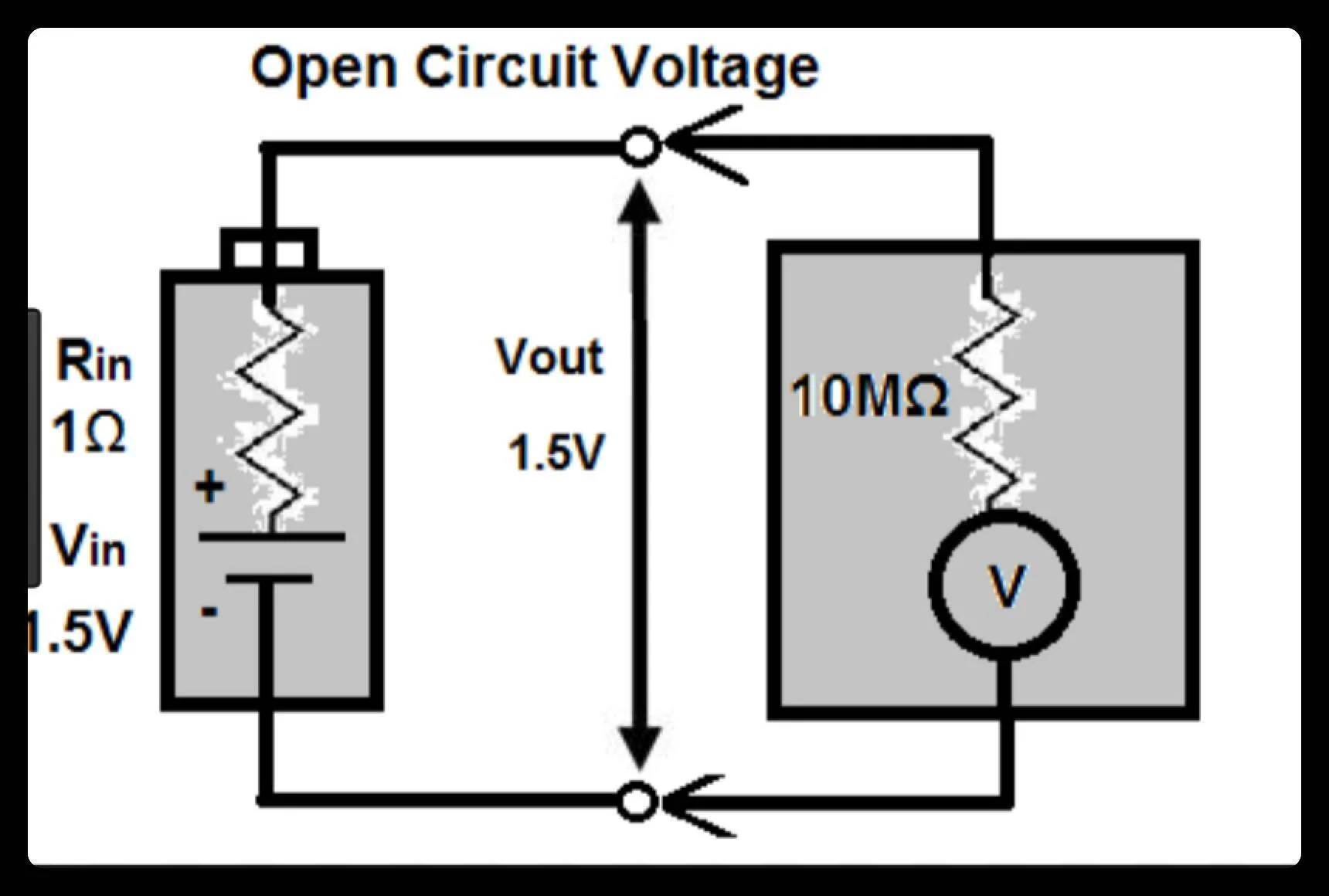
The voltmeter internal resistance/impedance forms a voltage divider as shown in below circuit.

Ford F-150 Lightning Generac 6853 trips truck GFCI voltmeter voltage divider

Because of this, the voltmeter will read slightly less voltage than actual open circuit voltage. This difference is error due to internal resistance/impedance of the voltmeter. This error will get smaller as the voltmeter internal resistance/impedance goes up.
 

v2h8484

Well-known member
Joined
Mar 3, 2023
Threads
3
Messages
211
Reaction score
109
Location
USA
Vehicles
Tesla Model 3
As I found in another test, when there is no utility power provided to the GENERAC, there is no voltage spike or trip of the truck GFCI.
This is expected and adds support to the likelihood of inductive kickback induced voltage transients from switch openings (automatic or manual) when the utility power is present. Remember there is a big inductor at you utility power source (i.e. the secondary winding of your neighborhood power distribution transformer).

High input impedance (even 1 mega ohm is high) voltage sensing in the voltmeter just illustrates the exaggeration of actual voltage transient magnitude but it does not affect how the truck behaves. However, similar high input impedance voltage sensing is likely in the truck and exaggerated voltage transient magnitude can cause the truck to incorrectly trip. In addition, induced voltage transients can cause current transients which in turn can trip poorly designed GFCI that doesn't filter out high frequency current transients like in the Lightning.
 
Last edited:
  • Like
Reactions: chl

P-38

Well-known member
First Name
Mike
Joined
Jan 28, 2025
Threads
2
Messages
110
Reaction score
68
Vehicles
2024 Lightning Lariat
I don't understand the exaggeration part of this:

High input impedance (even 1 mega ohm is high) voltage sensing in the voltmeter just illustrates the exaggeration of actual voltage transient magnitude but it does not affect how the truck behaves
The voltage is reaching that even if you don't have a voltmeter on there.
 

Sponsored

EVpower

Active member
First Name
Steve
Joined
Dec 24, 2023
Threads
2
Messages
44
Reaction score
42
Location
Northern California
Vehicles
2023 F-150 Lightning Lariat, Bronco II
Occupation
Electrical Engineer
The early post suggests that the transfer switch contactor solenoid coil is drawing current from the PPOB line to ground when the transfer to the truck is initiated on the Generac panel. This immediately trips the PPOB ground fault protection.

I would look for a wiring problem such as a swapped neutral between the utility source and gen generator (PPOB) inlet. It's also worth checking that both sides of the contactor coil receive 240 volts from the intended source through the auxiliary contacts on the contactor.

You can eliminate a transient spike causing the truck GFCI tripping by temporarily replacing the contactor coil with a resistive load like two light bulbs in series and repeating the test. If the PPOB GFCI still trips, then contactor coil spikes are not the cause of the problem.

Note that transients are produced by the removal of current through a coil. That didn't seem like what's happening. It's worth confirming.

Steve
 

v2h8484

Well-known member
Joined
Mar 3, 2023
Threads
3
Messages
211
Reaction score
109
Location
USA
Vehicles
Tesla Model 3
I don't understand the exaggeration part of this:
The voltmeter (and likely the voltage sensor in the truck) has high input impedance due to the designed internal resistance (R) and parasitic capacitances (C) coupled with the parasitic inductances (L) from the long test leads. This means fast transients will get exaggerated (amplified and distorted) due to the interactions of the RLC . If the internal resistance was lower then it would limit the spike peak and duration by damping the transient. But that would decrease the safety protection of the voltage sensing components when measuring high voltage. So, special tools and probing techniques are often used to accurately measure fast transient spikes. One common improvement would be to shortened the voltage sensing wires/leads to a few inches to minimize parasitic inductances but that's not always possible in all situations. For example, the truck voltage sensing wires could be long because the actual sensor is likely on a centralized circuit board with other components (typically for cost reasons) located physically far away from the measurement point.

There are ways to compensate for transients to avoid false/nusiance trips using additional transient filtering components with associated costs. Howerver, given that Ford seems to have implemented little/no transient filtering on the GFCI it's doubtful that they would have done it on the voltage sensor.

The voltage is reaching that even if you don't have a voltmeter on there.
Correct. As mentioned before, the voltmeter simply provides a visual demonstration of the issue but does not affect how the truck behaves. The truck is only affected by its own voltage sensor which likely suffers the same issue.
 

chl

Well-known member
First Name
CHRIS
Joined
Dec 16, 2022
Threads
6
Messages
1,919
Reaction score
1,132
Location
alexandria virginia
Vehicles
2001 FORD RANGER, 2023 F-150 LIGHTNING
The early post suggests that the transfer switch contactor solenoid coil is drawing current from the PPOB line to ground when the transfer to the truck is initiated on the Generac panel. This immediately trips the PPOB ground fault protection.

I would look for a wiring problem such as a swapped neutral between the utility source and gen generator (PPOB) inlet. It's also worth checking that both sides of the contactor coil receive 240 volts from the intended source through the auxiliary contacts on the contactor.

You can eliminate a transient spike causing the truck GFCI tripping by temporarily replacing the contactor coil with a resistive load like two light bulbs in series and repeating the test. If the PPOB GFCI still trips, then contactor coil spikes are not the cause of the problem.

Note that transients are produced by the removal of current through a coil. That didn't seem like what's happening. It's worth confirming.

Steve
Thanks Steve for your input.

I already checked the neutrals for a swapped one - none found. When I first wired the switch there was one neutral swapped - I had an unswitched circuit's neutral by mistake, but I found that and corrected it.

I also wondered if there was some other wiring mistake so I checked everything again. Ten hots, ten neutrals, one by one, all correct.

In generator position, 1) there is no continuity between the neutrals in the GENERAC and ground, and 2) there is no voltage wrt to ground on any transferred circuit lines when the breakers are closed and there is no generator providing power. That to me indicates there is no neutral or hot miswiring of the loads.

I did not check both sides of the solenoid coil for 240V. I don't think I need to check it because the solenoid works to switch between utility and generator and back with a different (gas) generator, so it has to be getting power on both sides.

With my gas generator ON and connected through the switch, the solenoid switches between utility and generator, and back, when both are available using the rocker switch to activate the solenoid, so there appears to be no issue there with the solenoid getting power on both sides. That gas generator does NOT have a GFCI breaker however I did test it with a bonding plug installed.

Another person had the same issue of tripping the Lightning with an install done by an electrician who doubled checked everything and has reached out to GENERAC about it - no further info though. So a wiring mistake is unlikely at this point. Unless it is something esoteric that we are missing.

Also, apparently solenoid coils causing spikes like this is not unusual in transfer switches - at least from a search I did yesterday. If I had doen that search to begin with it might have saved me some time, lol.

So it does appear to me it is the coil is the cause and it only happens when the utility power breaker to the GENERAC is on and supplying power.

When there is no utility power to the GENERAC, and the Lightning is connected, the switching to the Lightning does not trip the GFCI of the PPOB.

Also, when there is no utility power to the GENERAC, there is no voltage spike on the generator lines.

When connected to the PPOB, and the utility power is restored and provided to the GENERAC, switching to utility power from the PPOB trips the GFCI.

One cannot use the rocker switch to switch to utility if there is no utility power present, or to the PPOB is there is no power present on the GEN lines. The switching has to be manual which I did as well. With no utility power provided to the GENERAC, manually switching to the Lightning PPOB, and back, does not trip the GFCI.

I did not check for a voltage spike on the utility feed line to the GENERAC when switching from the Lightning but I suspect there would be one due to the solenoid coil.

I believe all of these switching tests I did with the PPOB were with no loads connected when switching. That is, all the breakers in the GENRAC were open at the time of switching.

After successfully switching to the PPOB either manually or with the rocker switch, I added the loads one-by-one, that is, I closed the breakers in the GENERAC one at a time until they were all closed. No fault occurred, no overload either.

As I may have mentioned, using my gas generator (with a bonding plug) I was able to use the rocker switch to transfer between utility and generator with a full load, that is all breakers in the GENERAC closed, without any problems. That gas generator does NOT have a GFCI breaker however.

At this point, I think the odds that my switch, and at least two other people's switches were all miswired and that is causing the Lightning PPOB to trip is unlikely.

It seems more likely to be inherent in the GENERAC switch that some transient voltage/current appears on the generator lines due to the solenoid during switching when there is utility present.

The voltage spike has the characteristics of a discharging coil transient. And the solenoid is the only thing in the GENERAC connected at time it occurs.

As I mentioned, that seems to be common with some transfer switches due to the solenoid according to a search I did yesterday.

The work around is: 1) be sure the utility power breaker to the GENERAC is OFF when switching to the PPOB, and 2) when switching back to utility, be sure to turn off the PPOB first.
 

chl

Well-known member
First Name
CHRIS
Joined
Dec 16, 2022
Threads
6
Messages
1,919
Reaction score
1,132
Location
alexandria virginia
Vehicles
2001 FORD RANGER, 2023 F-150 LIGHTNING
This is expected and adds support to the likelihood of inductive kickback induced voltage transients from switch openings (automatic or manual) when the utility power is present. Remember there is a big inductor at you utility power source (i.e. the secondary winding of your neighborhood power distribution transformer).

High input impedance (even 1 mega ohm is high) voltage sensing in the voltmeter just illustrates the exaggeration of actual voltage transient magnitude but it does not affect how the truck behaves. However, similar high input impedance voltage sensing is likely in the truck and exaggerated voltage transient magnitude can cause the truck to incorrectly trip. In addition, induced voltage transients can cause current transients which in turn can trip poorly designed GFCI that doesn't filter out high frequency current transients like in the Lightning.
I doubt the utility transformer is the source of the spike.

The power is NOT being removed from the coil of the utility transformer when I flip the transfer switch, so it's magnetic field is not collapsing from having power removed.

The source of the spike if it is a coil field collapsing, which it looks like, has to be a coil from which power is removed when the switch is flipped, and that is the solenoid coil.

When power is removed from a transformer primary coil, there can be a surge in the secondary coil, but I am not switching that. Also, utility transformers often have surge suppressors (snubbers) to dissipate surges and prevent damage to the transformer.

My other thought was the transfer switch might not be effectively break-before-make when switching which could cause a transient voltage spike.

However, while it could be a combination of both effects, from a search I did yesterday it seems more likely to be the solenoid which is a known issue in transfer switches.
 

v2h8484

Well-known member
Joined
Mar 3, 2023
Threads
3
Messages
211
Reaction score
109
Location
USA
Vehicles
Tesla Model 3
The power is NOT being removed from the coil of the utility transformer when I flip the transfer switch, so it's magnetic field is not collapsing from having power removed.
You would need to make relevant measurements to verify that to be certain. It appears the transfer switch has internal control circuitry to prevent switching to Generator if there is no generator power source while only Utility power is present. This suggests the transfer switch is using Utility power (e.g. voltage sensing, switch blocking, etc.) even if no external loads are connected. In addition, there are LED's that may also be using utility power. The power consumption current is likely low but inductive kickback is proportional to the rate of current change when the switch opens. So, even at low absolute current levels the rate of current change can be quite high when the switch opens.
 

Sponsored

chl

Well-known member
First Name
CHRIS
Joined
Dec 16, 2022
Threads
6
Messages
1,919
Reaction score
1,132
Location
alexandria virginia
Vehicles
2001 FORD RANGER, 2023 F-150 LIGHTNING
You would need to make relevant measurements to verify that to be certain. It appears the transfer switch has internal control circuitry to prevent switching to Generator if there is no generator power source while only Utility power is present. This suggests the transfer switch is using Utility power (e.g. voltage sensing, switch blocking, etc.) even if no external loads are connected. In addition, there are LED's that may also be using utility power. The power consumption current is likely low but inductive kickback is proportional to the rate of current change when the switch opens. So, even at low absolute current levels the rate of current change can be quite high when the switch opens.
Well think about this.

Yes, there is utility power on the solenoid coil which comes from a breaker in the service panel which of course comes from the utility transformer out in the neighborhood somewhere from a secondary of a transformer.

BUT, when I move the switch to the generator position the solenoid is no longer connected to the utility via the breaker-service panel-utility transformer-secondary, and there is no electrical path for a surge from the utility secondary to reach the generator lines even if one was created by the utility from switching.

On the other hand, in the generator position the solenoid IS connected to the generator lines to be powered by them so the collapsing field of the solenoid can cause the surge detected. During the test there was no power from any generator on the generator lines. If the Lightning had been connected, the GFCI breaker would have tripped because it would have detected the surge and interpreted it as a ground fault.

Also, take a step back and imagine if every time you unplugged something in your house or flipped a switch off, there was a significant transient from the utility transformer headed your way. It just ain't gonna happen.

Such relatively small load changes are not significant enough to cause the utility transformer to produce a measurable surge.

Of course things like refrigerators, AC compressors or motors could cause a measurable surge in your house system when going on and off, lights will dim for example if it is significant. It is their coil filed collapse that produces the surge in your house, but remember, they go on and off while still connected to your house wiring. The solenoid coil is disconnected from the utility side when switched, so the surge is only on the generator lines to which it is now connected.

What could cause utility surges that could be significant are things light lightning (not the Ford kind the sky kind), when the utility switches in and out supplies (grid switching), power outages and returns, or malfunctions.

Also, my whole house surge suppressor would take care of it since it can handle a whole heck of a lot of surge.
 

v2h8484

Well-known member
Joined
Mar 3, 2023
Threads
3
Messages
211
Reaction score
109
Location
USA
Vehicles
Tesla Model 3
BUT, when I move the switch to the generator position the solenoid is no longer connected to the utility via the breaker-service panel-utility transformer-secondary, and there is no electrical path for a surge from the utility secondary to reach the generator lines even if one was created by the utility from switching.
Transient spikes can easily get coupled via parasitic capacitances that are almost everywhere.

Also, my whole house surge suppressor would take care of it since it can handle a whole heck of a lot of surge.
There are many different types of surges/spikes. Whole house surge suppressors are for line to line/netural/ground spikes and typically only suppress voltages that are several hundred volts in magnitude. That's very different from the issue here which is voltage difference between neutral and earth ground which has a much lower tolerance (typically < 2V) for bonded neutral detection/protection circuitry.
Sponsored

 
Last edited:


Top