
ElectrifyingMe25
Well-known member
You can definitely use a VFD that's capable of single phase 240V input, and output 3-phase 220v. The VFD has to be bumped up in size to handle the conversion. Usually 1.5 to 2X the power rating to prevent overheating.Hi all,
I recently bought a three phase grinder, it was used so a very good deal! Figured a good way to run it would be via my lightning with the benefit of being able to run it from any location. However as best I know both the 120v plugs and the 240v are all single phase. I’m no electrician. Anyone have a suggestion on how to best do this and what plug type makes the most sense? Could not find any posts but I’m sure someone has solved this!
Thanks in advance!
Also, you definitely need a line reactor between your truck's 240V and the VFD input because all the VFDs generate harmonics as it's generating its three phase output. The harmonics are electrical noise with high voltage spikes. If you try to run the VFD without a line reactor you risk damaging the Inverter built into your truck that supplies 240V.
The VFD can be set up to output 220V through the configuration settings. Be sure to set the VFD settings according to your motor nameplate data. Input voltage, Hz, FLA, HP. output voltage.
Also, I noticed on the nameplate you showed, you have a dual voltage motor. It can be run on 220 or 440V 3-phase.
Check the guide I copied from Grok-3 to verify the motor set up for 220V operation. If it isn't already set up for 220V, follow the guide from Grok-3 below.
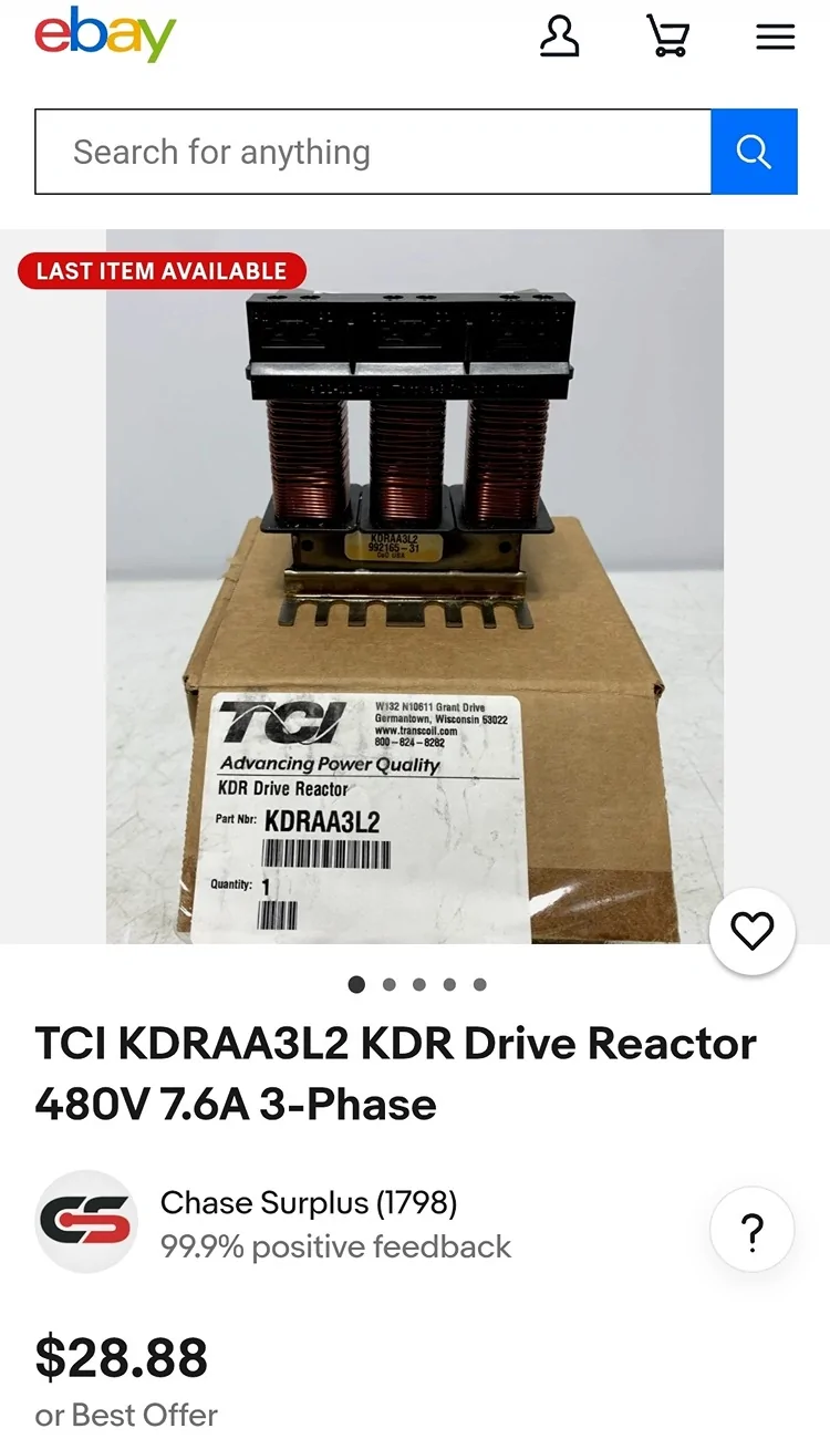
I have also included a picture/source for a line reactor. The line reactor needs to be rated for about 8A for a 1.5 to 2.0HP VFD with your application for a 1HP motor. A rating of 480V is good. Only connect L1 and L2. Leave L3 disconnected on the reactor. Remember, the line reactor connects to the single phase 240V, in between your receptacle and the VFD input.
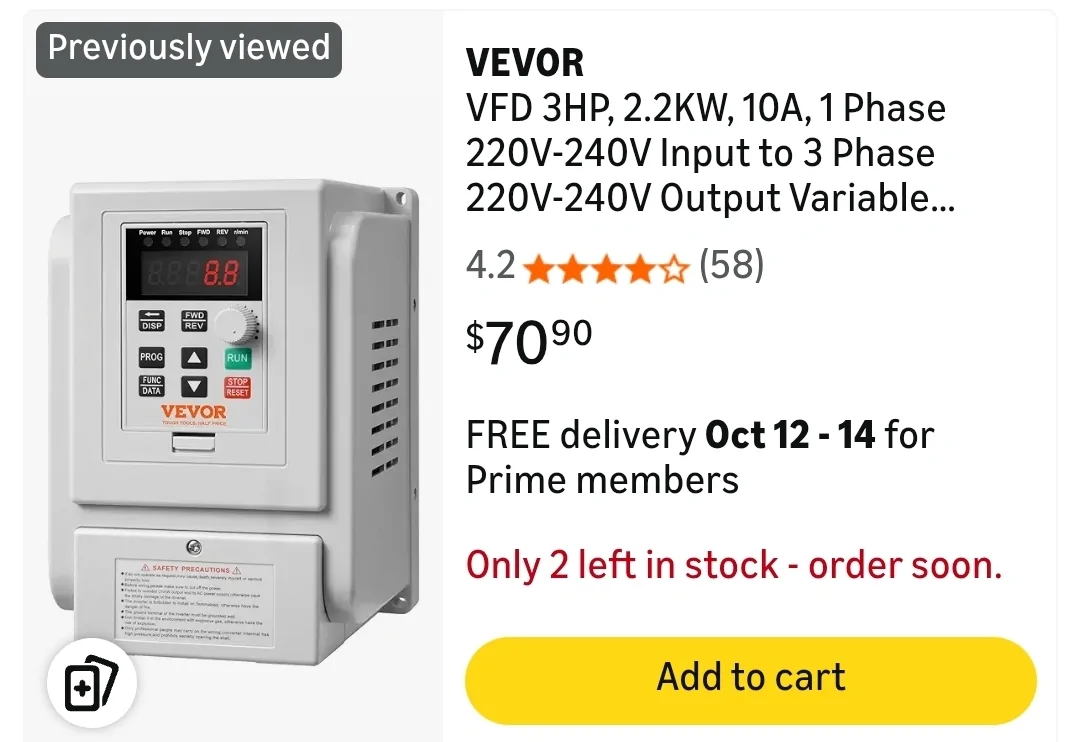
The picture of the drive I attached is a 2.3KW (3HP). It will work if you lower the settings to fit your motor nameplate numbers in the configuration. It is a 240V input type. If you can find one like it that's 1.5KW (2HP), that would fit better.
Here is the information from Grok-3:
If I have a 220v / 440v AC three phase motor, and if it was set up to run on 440v three phase, what wiring changes in the motor junction box do I need to make to run it on 220v 3-phase?
Answer:
To reconfigure a 220V/440V AC three-phase motor from 440V to 220V operation, you need to change the wiring in the motor's junction box to switch from a wye (star) connection (used for 440V) to a delta connection (used for 220V). This is because dual-voltage three-phase motors are typically designed to operate at the higher voltage (440V) in a wye configuration and the lower voltage (220V) in a delta configuration. Below are the general steps:Steps to Reconfigure the Motor WiringVerify the Motor Nameplate and Wiring Diagram:Check the motor’s nameplate or documentation for the specific wiring diagram for 220V (low voltage) and 440V (high voltage). The nameplate usually shows two connection diagrams: one for wye (440V) and one for delta (220V).
Ensure the motor is designed for dual-voltage operation (220V/440V). If it’s not, do not attempt to rewire it.
Power Off and Safety
 isconnect all power to the motor and ensure it is locked out/tagged out to prevent accidental energization.
Use a multimeter to confirm no voltage is present.
Access the Motor Junction Box:Open the motor’s junction box to access the terminal leads. A typical dual-voltage three-phase motor has 9 or 12 leads (commonly labeled T1 through T9 or T1 through T12).
Identify the Current Configuration:For 440V operation, the motor is likely wired in a wye (star) configuration. In this setup:Leads T4, T5, and T6 (or equivalent) are typically connected together to form the neutral point.
Power is applied to T1, T2, and T3 (the other ends of the windings).
The remaining leads (e.g., T7, T8, T9) are paired with T1, T2, and T3, respectively.
Rewire for 220V (Delta Configuration):To switch to 220V, reconfigure the leads to form a delta connection. For a 9-lead motor, the typical delta configuration is:Connect T1, T6, and T7 together (this forms one corner of the delta).
Connect T2, T4, and T8 together (another corner of the delta).
Connect T3, T5, and T9 together (the third corner of the delta).
Connect the three power lines (L1, L2, L3) to these three connection points:L1 to T1+T6+T7
L2 to T2+T4+T8
L3 to T3+T5+T9
If the motor has 12 leads, consult the motor’s wiring diagram, as the connections may involve additional steps or different lead pairings.
Secure Connections:Ensure all connections are tight and insulated using appropriate connectors (e.g., wire nuts or terminal blocks) rated for the motor’s current.
Double-check that no bare wires are exposed and that the connections match the delta configuration diagram.
Verify the Wiring:Compare your wiring to the motor’s 220V delta diagram.
Use a multimeter to check continuity and ensure there are no short circuits or incorrect connections.
Close the Junction Box and Test:Securely close the junction box.
Restore power and test the motor on a 220V three-phase supply. Monitor for proper operation (correct rotation, no excessive heat or noise).
Verify the motor’s current draw matches the nameplate rating for 220V operation (it will be higher than for 440V, typically double).
Key NotesCurrent Draw: At 220V (delta), the motor will draw approximately twice the current compared to 440V (wye). Ensure the power supply, wiring, and circuit protection are rated for the increased current.
Motor Leads: The exact lead numbers (e.g., T1–T9) may vary depending on the motor manufacturer. Always follow the motor’s specific wiring diagram.
Rotation Direction: Changing the wiring configuration typically does not affect the motor’s rotation direction, but verify it during testing. If rotation is incorrect, swap any two power lines (L1, L2, L3).
Professional Assistance: If you’re unsure or the motor has an unusual configuration (e.g., 12 leads or non-standard labeling), consult a qualified electrician or motor technician.
Example Wiring for a 9-Lead Motor440V (Wye):T4+T5+T6 connected together (neutral point).
L1 to T1+T7, L2 to T2+T8, L3 to T3+T9.
220V (Delta):T1+T6+T7 connected together, attach to L1.
T2+T4+T8 connected together, attach to L2.
T3+T5+T9 connected together, attach to L3.
If you have the motor’s specific wiring diagram or additional details (e.g., lead numbers, motor brand), I can provide more tailored guidance. Let me know if you need further assistance!
Sponsored
Last edited: