v2h8484
Well-known member
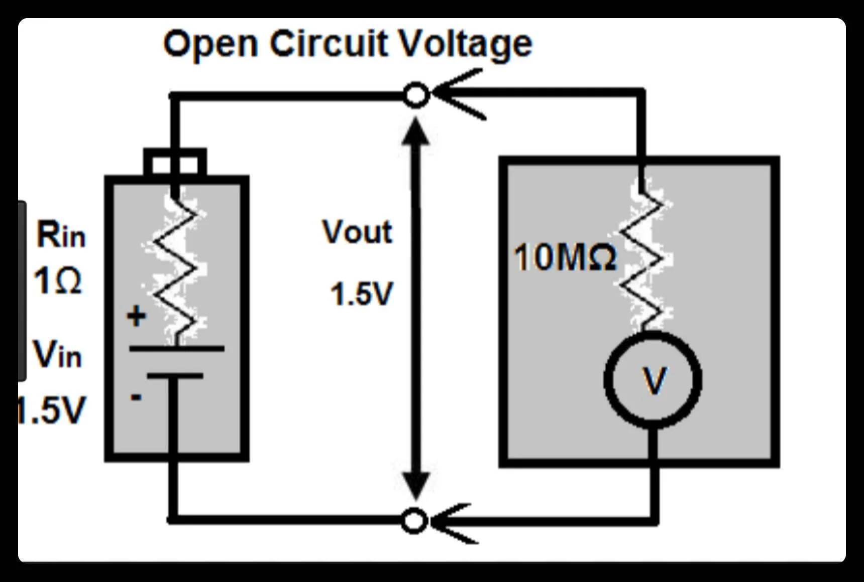
Given the cheap voltmeter with its high input impedance (likely > 10 Megohms) and long leads much of what you are seeing is probably greatly exaggerated. When the switch is opened (even manually) there could easily be an inductive kickback enough to induce the observed transients. Frankly, the truck is also likely using a high input impedance voltage sensor and suffers the same issue which is then made worse by its overly sensitive GFCI for a whole house.
Sponsored