Sponsored

Looking for fender NMO Antenna mount

  • Thread starter Deleted member 15218
  • Start date
  • Watchers 4

Deleted member 15218

Guest
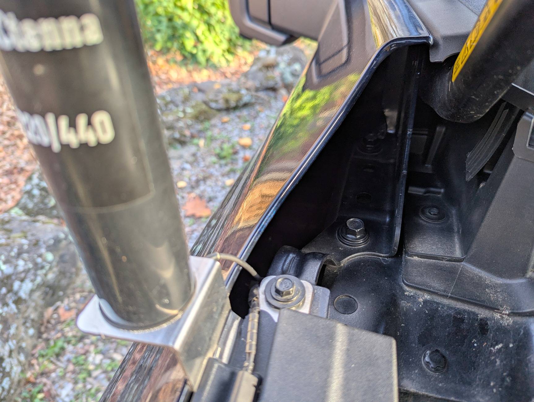
This message is generally for amateur radio operators. I'm trying to attach a 2M/UHF antenna to my 2023 Lightning XLT. A mag mount is a no-go as it won't stick to any surfaces. DX Engineering and others make an angle bracket that attaches to a 10 mm bolt on the driver's side finder. I just looked carefully at that area and I found the bolt but there is a plastic channel that comes right up to the bolt with a cable running through it. I guess that's so the frunk can be opened via the fob.

Any hams out there? How did you mount your antennas?

73,
Al, K7AR
Vancouver, WA
Sponsored


queuewho

Well-known member
Joined
Oct 27, 2022
Threads
5
Messages
577
Reaction score
632
Location
Western PA
Vehicles
22 F150 Lightning Lariat SR
Any hams out there? How did you mount your antennas?
Not a ham but I have been playing with meshtastic stuff lately... A few people have posted the bulletproofdiesel.com third brake light setup. Seems like a good option, though you won't be parking underground or in structures with it.
 
OP
OP

Deleted member 15218

Guest
Thanks those look like well made products but expensive. I'll consider it.

Al, K7AR
 

priceb

Well-known member
First Name
Price
Joined
May 31, 2023
Threads
2
Messages
122
Reaction score
127
Location
Western North Carolina
Vehicles
2023 F150 Lightning XLT SR
Occupation
College Instructor
OP
OP

Deleted member 15218

Guest
Thanks Price that's a great tip. I didn't think about cutting back the plastic trim. Have to be careful with that wire running thought it. I'll lookup the parts you used.

73,
Al, K7AR
 

Sponsored

TheSilverFlash

New member
First Name
Paul
Joined
Jan 23, 2026
Threads
0
Messages
4
Reaction score
0
Location
Diamondhead, MS
Vehicles
25 Flash
I used the Comet/NCG vehicle specific mount FO4ANTNCG-R (https://www.dxengineering.com/parts/cma-fo4antncg-r) paired with a Comet CK-3NMO cable assembly (https://www.dxengineering.com/parts/cma-ck-3nmo5)

I chose the passenger side variant as the Ford up-fitter guide recommends not installing amateur radio antennas on the driver's side fender.

As you can see in the photo below I had to remove the trim around the edge of the frunk, install the antenna mount and then reattach the trim.

PXL_20241109_212317136.jpg
How did you run the coax into the cab?
 

priceb

Well-known member
First Name
Price
Joined
May 31, 2023
Threads
2
Messages
122
Reaction score
127
Location
Western North Carolina
Vehicles
2023 F150 Lightning XLT SR
Occupation
College Instructor
How did you run the coax into the cab?
My truck is an XLT without power running boards. So there is an empty grommet under the passenger and driver floor board where power running board wiring would go. I ran power and coax through those grommets.
 

TheSilverFlash

New member
First Name
Paul
Joined
Jan 23, 2026
Threads
0
Messages
4
Reaction score
0
Location
Diamondhead, MS
Vehicles
25 Flash
My truck is an XLT without power running boards. So there is an empty grommet under the passenger and driver floor board where power running board wiring would go. I ran power and coax through those grommets.
Ok thanks, I think I see that grommet. How did you drop the coax down through the engine bay? Looks like maybe it can go down and behind the wheel arch covers (that felt-like material)? Did you use silicone sealant to waterproof the grommet?
 

K6CCC

Well-known member
First Name
Jim
Joined
Sep 12, 2024
Threads
31
Messages
1,105
Reaction score
1,147
Location
Glendora, Calif.
Vehicles
2024 Lightning Flash ER in Antimatter Blue w/9.6 PPO , 2017 Corolla (wife's car)
Occupation
Retired from 2-Way radio systems
I have a cab high fiberglass shell on my truck. I have three NMO mounts on the centerline of the shell. Of course since it's fiberglass I had to do something for a ground plane. Here's what I did - same thing that I did on the shell for my previous 2003 Dodge Ram 2500. The top of the shell is two layers of fiberglass with about a 3/8 inch space between them. In that space is a thin cardboard honeycomb mesh. I started by drilling a 1/4 inch hole at the desired location from the top through both layers of fiberglass. Then from the top using a 3/4 inch hole saw with a 1/4 inch pilot bit, I drill the top layer out to make it 3/4 inch. Then from the bottom side I use a 3 inch hole saw with a 1/4 inch pilot bit to make the bottom layer a 3 inch hole. Once the fiberglass is removed, use a screwdriver to small chisel to remove the cardboard from the area of the 3 inch hole. Note, while cutting the fiberglass I highly recommend goggles that seal around your eyes and good dust protection - you really don't want to breath the dust or get it in your eyes.

Next part is actually making the ground system. I got some fairly thin sheet copper from a local industrial metal supplier. Cut that into 2.5 inch circles with a 3/4 inch hole in the center. Because the fiberglass is thicker than a normal metal roof you have to use a thick surface mount. This is what I used:
https://www.arcantenna.com/products...low-loss-195-cable-n-male-rnmov-195-snm-c-17i
Install the antenna mount with the piece of copper plate on the bottom side of the upper fiberglass layer.

Next is to cut some radials from 12 AWG solid bare copper wire - I used eight, but that was likely overkill. Think about what band or bands you will ever used on that particular mount and cut the radials for the lowest frequency band. In my case the front and rear antennas are for 440 and the middle is going to be 2M. In the case of the short UHF radials, you can easily push the copper wire through the cardboard with needle nose pliers so that each radial wire has about a 3/8 inch of the wire overlapping the copper sheet. Now you will solder the radial wires to the copper. You MUST use a high heat iron or gun to do this, and I recommend applying flux before soldering. You really want the solder to be able to flow in just a couple seconds. Let each joint cool before starting the next to avoid remelting the adjacent joint. Use plenty of solder. Because you will be under the shell and you will almost certainly end up dropping molten solder, cover the bed of the truck and make damn sure you cant drop solder on you!

I said that the radials for UHF would push through the cardboard fairly easily. That was not the case for 2 meters. What I ended up doing was taking some 6-32 all thread I happened to have laying around and sort of sharpened one end with my bench grinder and chucked it up into a drill. With the all thread spinning from the drill it was fairly easy to push that through the cardboard. Once I pulled out the all thread, it was easy enough to push the 19 inch radials through the holes in the cardboard that the all thread had created.

The last step was routing the cables. I got some of the plastic cable anchors that have a screw to hold them in place. Use short #6 pan head sheet metal screws to hold the anchors to the lower layer of fiberglass. I found it easier to pilot hole the fiberglass before inserting the screws. I routed the cables to the driver side front of the shell. At the bottom of the shell (top of the bed) elevation there is a coax connector so I can disconnect the cables for when I remove the shell. To get the cables into the cab. I found that there is a plastic knockout on each side of the front wall of the bed near the bottom on each side. Remove the knockout and drill a hole in the back wall of the cab that lines up with the knockout. I installed a short piece of 1 inch conduit through the back wall of the cab such that the end of the conduit is just short of the knockout, and drilled a hole in the knockout that lines up with the end of the conduit. The idea is that there is no rigid mount between the back wall of the cab and front wall of the bed.

One of these days I will get the headliner pulled down and a few normal NMO mounts will go on the cab roof - but I have not gotten there yet.
 

TheSilverFlash

New member
First Name
Paul
Joined
Jan 23, 2026
Threads
0
Messages
4
Reaction score
0
Location
Diamondhead, MS
Vehicles
25 Flash
I have a cab high fiberglass shell on my truck. I have three NMO mounts on the centerline of the shell. Of course since it's fiberglass I had to do something for a ground plane. Here's what I did - same thing that I did on the shell for my previous 2003 Dodge Ram 2500. The top of the shell is two layers of fiberglass with about a 3/8 inch space between them. In that space is a thin cardboard honeycomb mesh. I started by drilling a 1/4 inch hole at the desired location from the top through both layers of fiberglass. Then from the top using a 3/4 inch hole saw with a 1/4 inch pilot bit, I drill the top layer out to make it 3/4 inch. Then from the bottom side I use a 3 inch hole saw with a 1/4 inch pilot bit to make the bottom layer a 3 inch hole. Once the fiberglass is removed, use a screwdriver to small chisel to remove the cardboard from the area of the 3 inch hole. Note, while cutting the fiberglass I highly recommend goggles that seal around your eyes and good dust protection - you really don't want to breath the dust or get it in your eyes.

Next part is actually making the ground system. I got some fairly thin sheet copper from a local industrial metal supplier. Cut that into 2.5 inch circles with a 3/4 inch hole in the center. Because the fiberglass is thicker than a normal metal roof you have to use a thick surface mount. This is what I used:
https://www.arcantenna.com/products...low-loss-195-cable-n-male-rnmov-195-snm-c-17i
Install the antenna mount with the piece of copper plate on the bottom side of the upper fiberglass layer.

Next is to cut some radials from 12 AWG solid bare copper wire - I used eight, but that was likely overkill. Think about what band or bands you will ever used on that particular mount and cut the radials for the lowest frequency band. In my case the front and rear antennas are for 440 and the middle is going to be 2M. In the case of the short UHF radials, you can easily push the copper wire through the cardboard with needle nose pliers so that each radial wire has about a 3/8 inch of the wire overlapping the copper sheet. Now you will solder the radial wires to the copper. You MUST use a high heat iron or gun to do this, and I recommend applying flux before soldering. You really want the solder to be able to flow in just a couple seconds. Let each joint cool before starting the next to avoid remelting the adjacent joint. Use plenty of solder. Because you will be under the shell and you will almost certainly end up dropping molten solder, cover the bed of the truck and make damn sure you cant drop solder on you!

I said that the radials for UHF would push through the cardboard fairly easily. That was not the case for 2 meters. What I ended up doing was taking some 6-32 all thread I happened to have laying around and sort of sharpened one end with my bench grinder and chucked it up into a drill. With the all thread spinning from the drill it was fairly easy to push that through the cardboard. Once I pulled out the all thread, it was easy enough to push the 19 inch radials through the holes in the cardboard that the all thread had created.

The last step was routing the cables. I got some of the plastic cable anchors that have a screw to hold them in place. Use short #6 pan head sheet metal screws to hold the anchors to the lower layer of fiberglass. I found it easier to pilot hole the fiberglass before inserting the screws. I routed the cables to the driver side front of the shell. At the bottom of the shell (top of the bed) elevation there is a coax connector so I can disconnect the cables for when I remove the shell. To get the cables into the cab. I found that there is a plastic knockout on each side of the front wall of the bed near the bottom on each side. Remove the knockout and drill a hole in the back wall of the cab that lines up with the knockout. I installed a short piece of 1 inch conduit through the back wall of the cab such that the end of the conduit is just short of the knockout, and drilled a hole in the knockout that lines up with the end of the conduit. The idea is that there is no rigid mount between the back wall of the cab and front wall of the bed.

One of these days I will get the headliner pulled down and a few normal NMO mounts will go on the cab roof - but I have not gotten there yet.
That sounds like a ton of work and unnecessary modification/fabrication when you could have simply used a ground independent mobile antenna like the Comet SBB5/GI190 or similar.
 

Sponsored

K6CCC

Well-known member
First Name
Jim
Joined
Sep 12, 2024
Threads
31
Messages
1,105
Reaction score
1,147
Location
Glendora, Calif.
Vehicles
2024 Lightning Flash ER in Antimatter Blue w/9.6 PPO , 2017 Corolla (wife's car)
Occupation
Retired from 2-Way radio systems
That sounds like a ton of work and unnecessary modification/fabrication when you could have simply used a ground independent mobile antenna like the Comet SBB5/GI190 or similar.
Except that's a 28 inch long antenna with is a huge issue in parking structures. A six inch UHF antenna is not too bad and a 2M quarter wave will bend enough going under the beams of a parking structure. And no, when you have eight antennas, removing them every time you go into a parking structure is NOT practical!

And BTW, most of the ground independent antennas are not as good as they would like you to believe. This is particularly true as frequencies get lower. Not too bad at 800 and 900 MHz, but pretty crappy at VHF. Note that I spent my last 21 years working in a city radio shop where we needed to install MANY strange antenna situations. We did some pretty detailed testing on most of them to see how well they really worked. Radiation patterns get really strange on some of the completely covert antennas we put onto undercover PD cars. And no, just because it gets a good SWR does NOT mean that it radiates worth a damn.
 

priceb

Well-known member
First Name
Price
Joined
May 31, 2023
Threads
2
Messages
122
Reaction score
127
Location
Western North Carolina
Vehicles
2023 F150 Lightning XLT SR
Occupation
College Instructor
Ok thanks, I think I see that grommet. How did you drop the coax down through the engine bay? Looks like maybe it can go down and behind the wheel arch covers (that felt-like material)? Did you use silicone sealant to waterproof the grommet?
I routed it along the felt wheel arch covers. At the end of the arch I slipped it through a gap at the end of the fabric. I didn't add any silicone, but I made the hole in the grommet smaller than the wire/coaxand put ends on after all the wire/coax was routed.
 

TheSilverFlash

New member
First Name
Paul
Joined
Jan 23, 2026
Threads
0
Messages
4
Reaction score
0
Location
Diamondhead, MS
Vehicles
25 Flash
I routed it along the felt wheel arch covers. At the end of the arch I slipped it through a gap at the end of the fabric. I didn't add any silicone, but I made the hole in the grommet smaller than the wire/coaxand put ends on after all the wire/coax was routed.
Thanks, that helps a lot! I think I can do this! 😆
Sponsored


Top