
tearitupsports
Well-known member
- First Name
- Russell
- Joined
- Jun 1, 2024
- Threads
- 13
- Messages
- 460
- Reaction score
- 523
- Location
- Cypress, TX
- Vehicles
- 2023 F-150 Lightning Lariat ER
- Occupation
- Industrial Automation & Controls
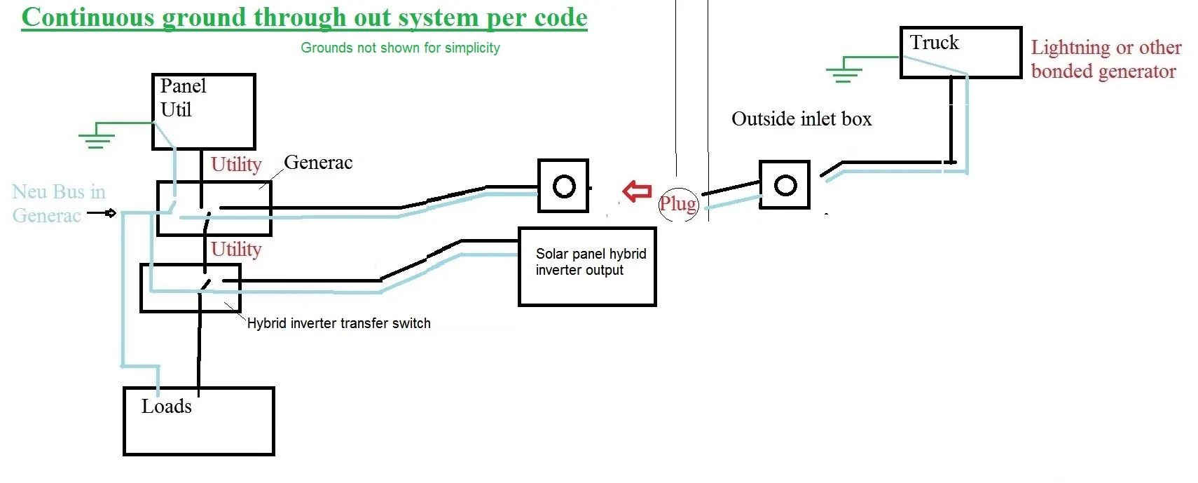
You keep going back to the Generac system, which is great for those who want that, but it not (on the surface) compatible with the original topic. The Generac transfer switch does not work with Hybrid inverter systems that have an automation transfer switch with generator input. The question at hand is how to make the truck properly and safely work with a Franklin or other brand generator input, where the truck is not the sole source of power, and the entire house loads are still wired to the main, or backup panel. If you can think of a proper wiring scheme to make the Generac work with these sytems, that would be more useful.Upon further reflection...
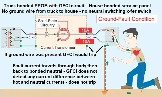
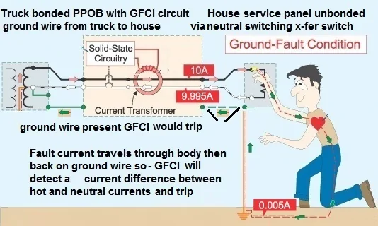
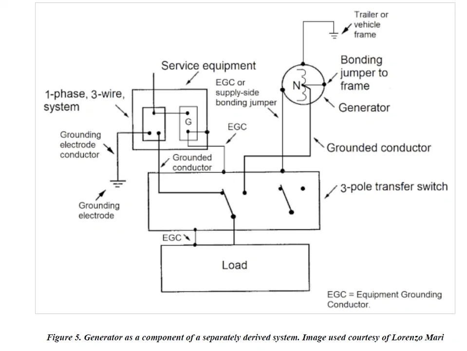
Perhaps the grounding electrode system of the house to which the Lightning ground system is connected would suffice as the code required "grounding electrode system," as apparently shown by Lorenzo Mari in the figure below, who is an expert in grounding systems - see his bio below. After all it is "connected to the ground terminal on the portable generator" (Lightning PPOB) via the ground wire through the GENERAC and the service panel.
However, since there are apparently conflicting opinions on this, I would err on the side of another grounding electrode system near the truck.
So, I wonder where would be a good place to connect a grounding electrode conductor to the Lightning?
Portable generators often provide an easily accessible ground lug suitable for earth grounding connections. Somewhere easily accessible near the PPOB outlet at the back of the truck would be best.
Has anyone made a grounding connection for a ground rod on their Lightning?
---------------------------
OPTIONAL Background follows
---------------------------
GENERAC transfer switch with a bonded generator - grounding requirements
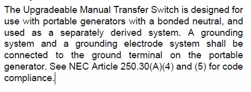
The GENERAC 6853 transfer switch manual says about grounding requirements for use with a bonded generator as a separately derived system:

"...A 'grounding system' and a 'grounding electrode system' shall be 'connected to the ground terminal' on the portable generator. See NEC Article 250.34(A)(4) and (5) for code compliance."
In the NEC, a "grounding electrode system" is the composite of "all installed grounding electrodes" at a building or structure that are bonded together "to provide a low-impedance path to the earth."
The NEC contains a list of items that are permitted to be used as grounding electrodes and requires that if any are present, they must all be used to form the "grounding electrode system."
So all grounding electrodes present at a building or structure should be bonded together to form a single, interconnected "grounding electrode system." And if multiple grounding electrodes are installed at a location, they must all be connected to create one unified system.
There are 8 items that are listed in 250.52 as allowable grounding electrodes: Metal Underground Water Pipe, Concrete-encased Electrode, Metal In-ground Support Structure, Ground Ring, Rod and Pipe Electrodes, Plate Electrodes, Other Listed Electrodes, Other local underground metal systems or structures
Equipment Grounding: This requires connecting non-current-carrying metal parts of the electrical system, like metal boxes, conduits, and appliance frames, to ground.
Grounding System: This comprises all ground wiring, equipment grounding, and generally includes the grounding of the neutral of the electrical system. The purpose is to help stabilize system voltages and aid operation of over-current protection devices during a fault.
A generator equipment frame (e.g., the Lightning chassis) is permitted to be the "grounding system." And on the Lightning, the neutral is bonded to the frame and is part of the grounding system. This "grounding system" is connected to the ground terminal of the Lightning in compliance with code.
Further, when the ProPower OnBoard (PPOB) is powering the house through the GENERAC transfer switch, the "grounding system" via the ground terminal of the PPOB outlet is connected to the GENERAC ground bus, which is in turn connected to the house panel ground bus as in figure 5 below.
The house panel ground bus is connected to a "grounding electrode system," which in my house comprises several outdoor ground rods and an underground cold water pipe.
The NEC requires a "grounding electrode system" for bonded generators when used as a separately derived system, e.g., the Lightning PPOB powering a house. Typically one would see this in the form of a "nearby" ground rod pounded into the earth and connected by a wire to the generator frame.
From what I have read recently, the "nearby" requirement has been loosened/removed and the "grounding electrode system" can be some distance away as long as it provides a low impedance ground path to the earth.
Since the Lightning neutral is bonded to the frame, and the frame is connected to the ground terminal, and the ground terminal is connected to the house "grounding electrode system" and these provide a low impedance path to the earth, then, is a second "grounding electrode system" connected to the Lightning frame required?
Some would say yes, others would apparently say no. The NEC goes through periodic updates and changes, so perhaps that explains why older versions and posts/videos about it, require a nearby grounding electrode connected to the generator frame.
A recent figure by Lorenzo Mari, Figure 5 below, shows what is purported to be a system compliant with the recent NEC code (2023 version) where no additional nearby "grounding electrode system" for the generator is provided (no nearby ground rod to frame). Also note his bio at the end of this post.

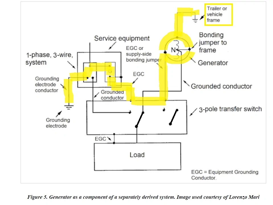
The generator grounding electrode system is apparently the grounding electrode at the service equipment (panel).
The "grounding electrode system" from the generator to the grounding electrode has been highlighted in yellow below (the transfer switch in the highlighted image is shown in the generator connected mode where the grounded conductor - neutral - is switched to the load and not directly connected to the utility neutral).
But...
Regardless of Lorenzo Mari's Figure 5 and his expertise, if I want to provide a nearby grounding electrode system for the Lightning, where would be a good place to connect a grounding electrode conductor to the Lightning?
By "good" I mean - easily accessible for connecting to a grounding electrode conductor (#6 wire) and making a good electrical connection to the Lightning chassis (generator frame).
------
BIO: Lorenzo Mari holds a Master of Science degree in Electric Power Engineering from Rensselaer Polytechnic Institute (RPI). He has been a university professor since 1982, teaching topics as electric circuit analysis, electric machinery, power system analysis, and power system grounding.
As such, he has written many articles to be used by students as learning tools. He also created five courses to be taught to electrical engineers in career development programs, i.e., Electrical Installations in Hazardous Locations, National Electrical Code, Electric Machinery, Power and Electronic Grounding Systems and Electric Power Substations Design. As a professional engineer, Mari has written dozens of technical specifications and other documents regarding electrical equipment and installations for major oil, gas and petrochemical capital projects. He has been EPCC Project Manager for some large oil, gas & petrochemical capital projects where he wrote many managerial documents commonly used in this kind of works.
In a few years, the bi-directional charger will be the proper and elagant solution.
Sponsored