RLXXI
Well-known member
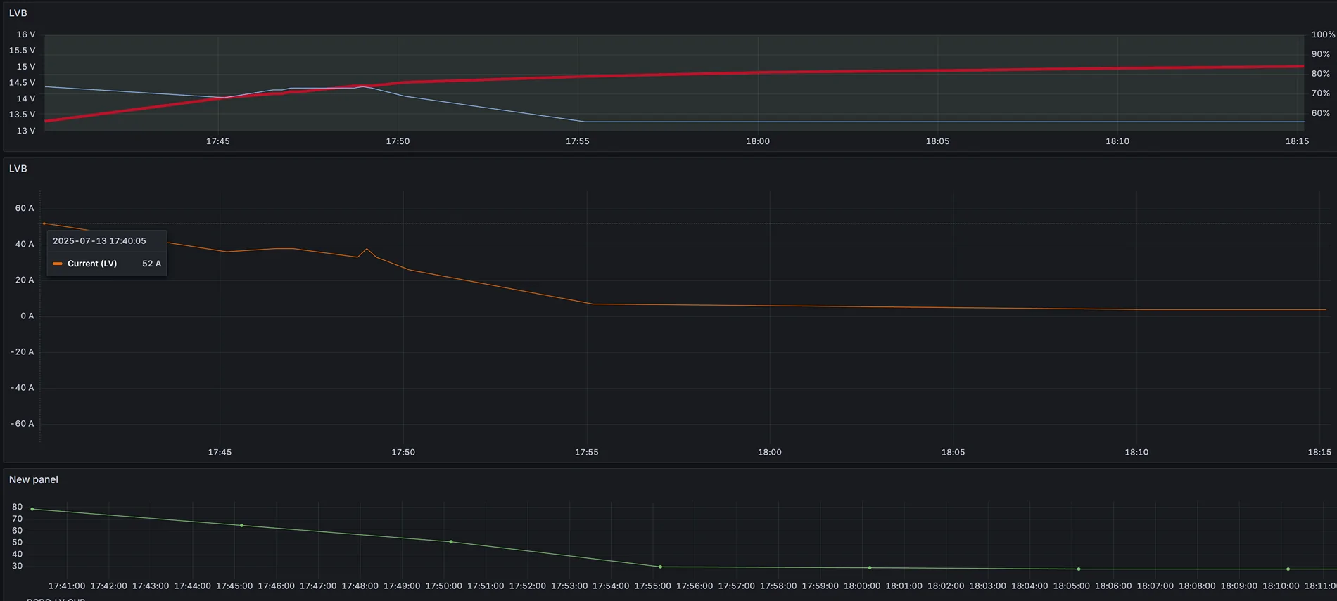
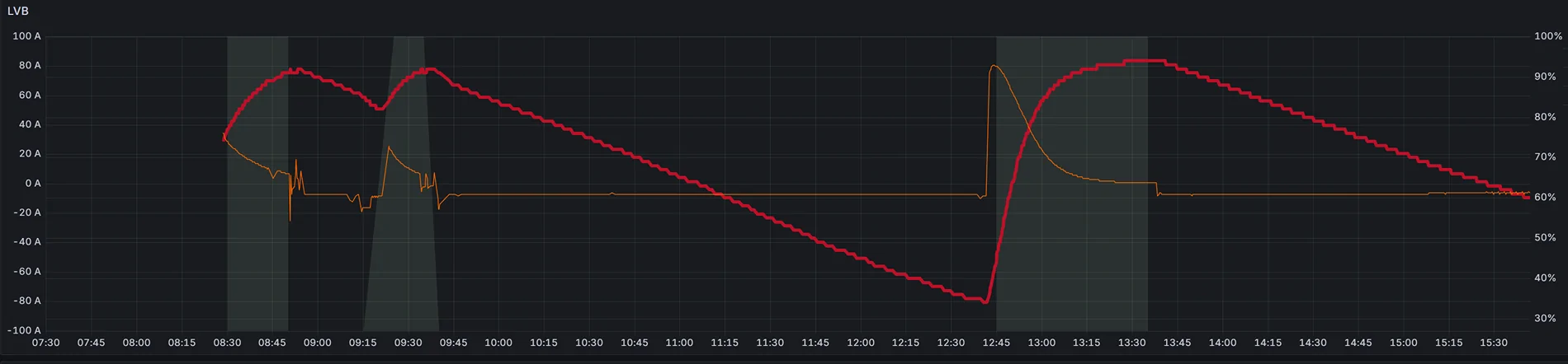
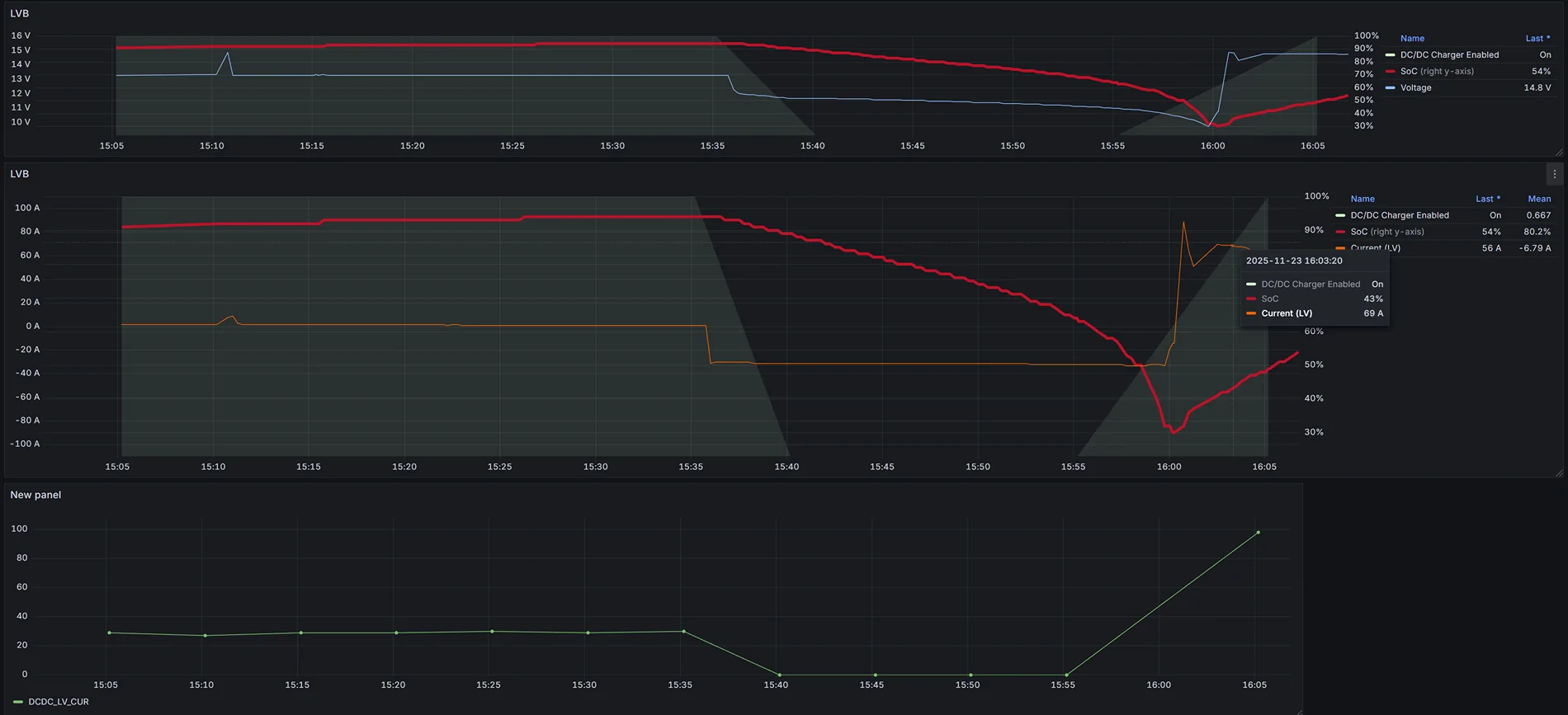
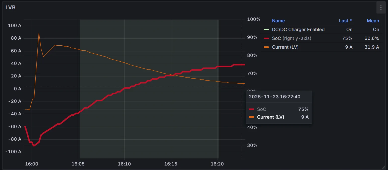
According the the Ford wsm for 25 ym, " Depending on the vehicle and environmental conditions, the DCDC is capable of outputting as many as 260 amps to the 12-volt battery. "On an associated 12 volt battery topic ... I am curious what others have seen regarding the charging current to their 12 volt battery. Using the Car Scanner app on CarPlay, I recorded 43 amps. On another short trip, which I did not record, I seem to remember 72 amps. Has anyone else recorded or observed their charging 12 volt charging amps?
Sponsored