Sponsored

Comma AI self driver assistant

UncleTony

Well-known member
First Name
Tony
Joined
Apr 18, 2025
Threads
0
Messages
58
Reaction score
80
Vehicles
2023 Lightning Lariat
Occupation
Cybersecurity Engineer
Hi everyone,


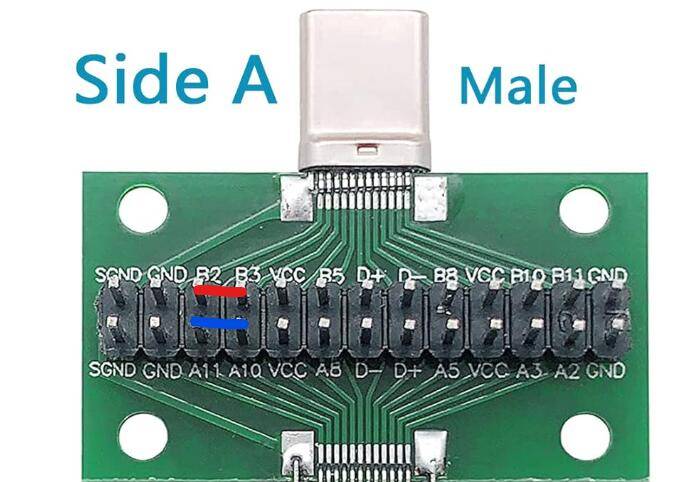
During a recent root cause analysis, I identified that the inclusion of a second resistor in earlier versions of the harness/breakout board may result in lower-than-expected resistance. While this is unlikely to cause issues under normal conditions, there is a theoretical risk that it could affect the performance or longevity of certain vehicle modules.


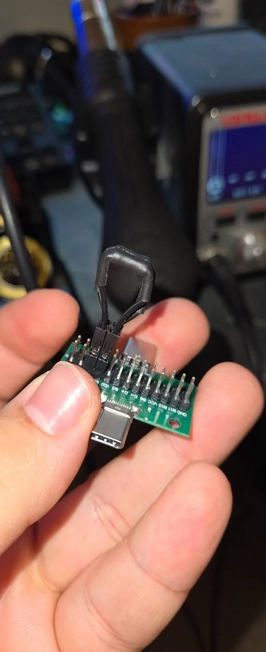
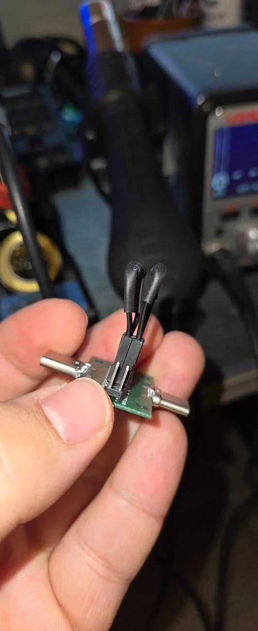
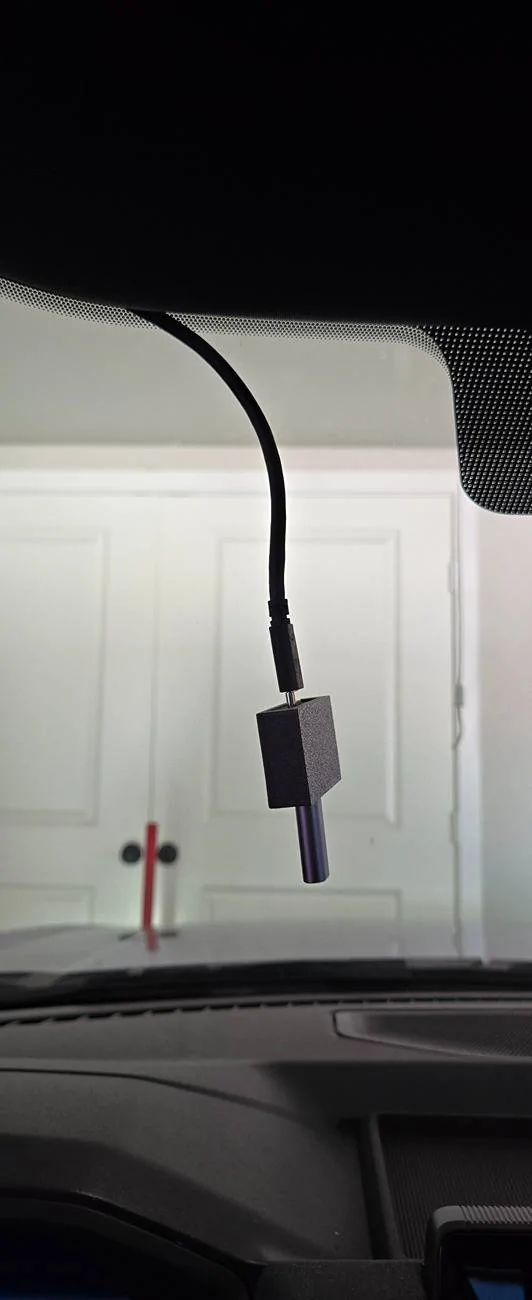
To clarify: this second resistor is not necessary and has been removed from all current breakout boards and the design sent to production. The updated boards are enclosed in a matte black, glass fiber ASA case for easy identification.


If you previously received a breakout board from me housed in a shiny black case and would like to have the second resistor removed, feel free to contact me. I'm happy to discuss options for updating your unit.


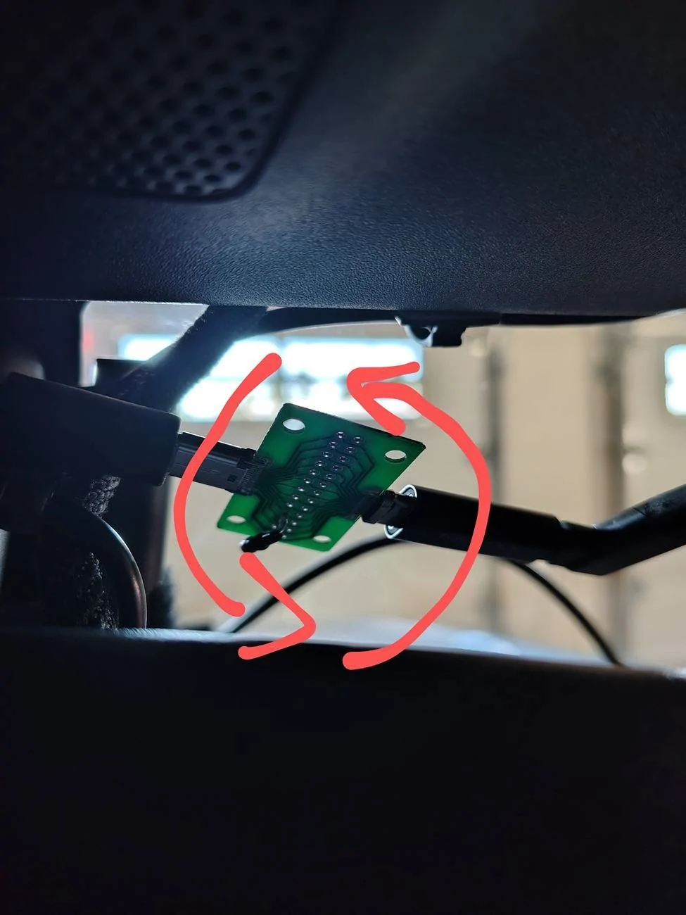
Just sharing this for transparency so you can make an informed decision about your setup.
Sponsored


B177y

Well-known member
First Name
Bill
Joined
Jul 16, 2024
Threads
11
Messages
407
Reaction score
482
Location
Oly Pen, WA
Vehicles
2024 Pro ER Max Tow
Just adding this in case anyone wants to get rid of the can bus errors and doesn't already have the custom harness. This is to be done at your own risk as I have only tested it for about 50 miles so far.

You just need these breakouts https://a.co/d/hFHdHoM as well as these resistors (as suggested by @Ajzride) https://a.co/d/h7GIwWR.

All you have to do is bridge B2 to B3 and A10 to A11 with the 62 ohm resistor on the breakout board. I would strongly suggest cutting the wire down as much as you can and solder the resistor into the wire. I would also not suggest you use this as a long term solution, but could save you from spending more or modifying your existing harness while the PCB gets worked out.

Everything you need outside of the resistors and what you need to solder is included in the kit.


1746493542323-gb.jpg


Edit to add what mine looks like when complete now that I've had the time to solder it properly.

20250505_212315.jpg


20250505_212318.jpg
Can you elaborate on exactly which resistors need to come off the breakout board?

I made my own and have more breakouts as well as a package of the 62 and 110 ohm resistors. I can correct my current board or make a new one until the professional ones arrive.
 

UncleTony

Well-known member
First Name
Tony
Joined
Apr 18, 2025
Threads
0
Messages
58
Reaction score
80
Vehicles
2023 Lightning Lariat
Occupation
Cybersecurity Engineer
Can you elaborate on exactly which resistors need to come off the breakout board?

I made my own and have more breakouts as well as a package of the 62 and 110 ohm resistors. I can correct my current board or make a new one until the professional ones arrive.
Remove the resistor that is across b2 and b3. You should only have a 120 ohm 1/4w resistor between a10 and a11.
 

B177y

Well-known member
First Name
Bill
Joined
Jul 16, 2024
Threads
11
Messages
407
Reaction score
482
Location
Oly Pen, WA
Vehicles
2024 Pro ER Max Tow
Remove the resistor that is across b2 and b3. You should only have a 120 ohm 1/4w resistor between a10 and a11.
Thanks! On my to-do list tomorrow.

I should have said that I have the 120 ohm where I said 110 above. Time for sleep.
 

B177y

Well-known member
First Name
Bill
Joined
Jul 16, 2024
Threads
11
Messages
407
Reaction score
482
Location
Oly Pen, WA
Vehicles
2024 Pro ER Max Tow
Remove the resistor that is across b2 and b3. You should only have a 120 ohm 1/4w resistor between a10 and a11.
I made a board with the resistor between a10 and a11 and I get the startup errors.

If I put the resistor between b2 and b3, no errors.

Are you sure that it's supposed to be between a10 and a11 or do I have something else happening?
 

Sponsored

UncleTony

Well-known member
First Name
Tony
Joined
Apr 18, 2025
Threads
0
Messages
58
Reaction score
80
Vehicles
2023 Lightning Lariat
Occupation
Cybersecurity Engineer
I made a board with the resistor between a10 and a11 and I get the startup errors.

If I put the resistor between b2 and b3, no errors.

Are you sure that it's supposed to be between a10 and a11 or do I have something else happening?
What breakout boards are you using?
 

B177y

Well-known member
First Name
Bill
Joined
Jul 16, 2024
Threads
11
Messages
407
Reaction score
482
Location
Oly Pen, WA
Vehicles
2024 Pro ER Max Tow
The Amazon boards and resistors from the parts list. I quoted you above in post 497. That list. I have a board with the pegs that I can move the resistors and I soldered a resistor between a10 and a11 on one of the solder boards. I got the error on the solder board then went back to the peg board and got the errors between a10-a11. Moved the resistor to pegs b2-b3 and no error.
 

Ajzride

Well-known member
First Name
Alan
Joined
Jun 6, 2021
Threads
4
Messages
474
Reaction score
336
Location
Houston
Vehicles
21Mach-E / 65Mustang / 21PB 502A 157"
Occupation
Eng
The Amazon boards and resistors from the parts list. I quoted you above in post 497. That list. I have a board with the pegs that I can move the resistors and I soldered a resistor between a10 and a11 on one of the solder boards. I got the error on the solder board then went back to the peg board and got the errors between a10-a11. Moved the resistor to pegs b2-b3 and no error.
Take the board with only a10-11 and flip it upside down to see if the errors clear.
 

UncleTony

Well-known member
First Name
Tony
Joined
Apr 18, 2025
Threads
0
Messages
58
Reaction score
80
Vehicles
2023 Lightning Lariat
Occupation
Cybersecurity Engineer
Take the board with only a10-11 and flip it upside down to see if the errors clear.
It shouldn't make a difference. I tested both directions over a10 and a11. I will have to test with the boards with the GPIO. I wonder if they aren't 1:1 pass through.
 

B177y

Well-known member
First Name
Bill
Joined
Jul 16, 2024
Threads
11
Messages
407
Reaction score
482
Location
Oly Pen, WA
Vehicles
2024 Pro ER Max Tow
That worked
Ford F-150 Lightning Comma AI self driver assistant 1000000979
That worked. I flipped it in the direction of the picture.

What's the game plan from here, other that leaving it in this orientation?
 

Sponsored

B177y

Well-known member
First Name
Bill
Joined
Jul 16, 2024
Threads
11
Messages
407
Reaction score
482
Location
Oly Pen, WA
Vehicles
2024 Pro ER Max Tow
I should add that "A" and the resistor are now on the side where the USB cable goes to the IPMA.
 

UncleTony

Well-known member
First Name
Tony
Joined
Apr 18, 2025
Threads
0
Messages
58
Reaction score
80
Vehicles
2023 Lightning Lariat
Occupation
Cybersecurity Engineer
That worked
1000000979.jpg
That worked. I flipped it in the direction of the picture.

What's the game plan from here, other that leaving it in this orientation?
Let me get home and test more. Curious why yours cares about what orientation its in.

Are you using comma power? Comma 3x, q4 harness?
 

UncleTony

Well-known member
First Name
Tony
Joined
Apr 18, 2025
Threads
0
Messages
58
Reaction score
80
Vehicles
2023 Lightning Lariat
Occupation
Cybersecurity Engineer
Comma 3x, q4 harness.

I have the OBD power attached, max off-road set to 2hs so it can upload when I get home.
I was able to recreate the issue with female to female adapter on the ipma side. Switch your breakout board so the female side goes to the ipma. I have a theory to what causes this. But ill have to pin it out to verify.
 

UncleTony

Well-known member
First Name
Tony
Joined
Apr 18, 2025
Threads
0
Messages
58
Reaction score
80
Vehicles
2023 Lightning Lariat
Occupation
Cybersecurity Engineer
I was able to recreate the issue with female to female adapter on the ipma side. Switch your breakout board so the female side goes to the ipma. I have a theory to what causes this. But ill have to pin it out to verify.
Should be installed like this.
Ford F-150 Lightning Comma AI self driver assistant 20250706_125322
Sponsored


Top